


1. Installation (16)
- Right-click the EnergyPro executable or icon and go to Properties.
- Select the Compatibility tab.
- Check “Disable fullscreen optimizations”.
- Click the button “Change High DPI settings”.
- Check “High DPI scaling override” performed by “Application”.
This error is caused by one of three things:
1. You installed EnergyPro as the Admin (or some other user) account but are now logging on as a different user. These files are installed into the Documents folder belonging to the user who installed the software and will not be accessible to other users due to Windows security protocols. You must install the software while logged on as the user who will be using it.
2. When you installed the software, the user account you installed under did not have sufficient security privileges to allow the software to create these files under the Documents\EnergyPro X\Libraries folder. You need to adjust the security privileges to allow that user account full access to that folder.
3. You have your Documents folder located on a virtual or cloud drive such as One Drive, Google Drive or DropBox. The Documents folder is where the EnergyPro Libraries are installed and these files must be located on the local computer drive. We suggest you remove or disable the virtual drive prior to installing.
In all cases this will require you correct the problem and then reinstall EnergyPro so these library files can be installed.
One of two things is causing this problem. The first possibility is that EnergyPro is unable to save the “license.lic” file onto your computer. That is the file that activates the software and is stored under the folder Program Data\EnergySoft\EnergyProX”. Either you do not have the appropriate security rights on the computer to save the file, or you have some security software active that is blocking the saving of that file. You should deactivate the software and/or modify your security rights to allow for that file to be saved.
The second possibility is that you have security software that is sweeping your computer clean, thus while EnergyPro is able to save the file, the software is then removing that file, assuming it is placed there as a virus. This software should not remove the file to prevent this.
To remove a license key from a computer, go to Help > Software Activation and click on Uninstall License.
You can purchase an additional seat for your EnergyPro license by contacting EnergySoft. Once the transaction is complete and the additional seat is added, install the software on the new computer from EnergySoft.com. Open EnergyPro and enter in the same license key to the new computer.
Digital signatures can be added to your reports by placing a .jpg file of your signature in the forms folder. The forms folder is located under: C:\Program Files\EnergySoft\EnergyPro X\Forms. The file you save in the forms folder needs to have the EXACT name: signature.jpg. Not signature.jpg.jpg. The JPEG needs to be just large enough to encompass the signature. If you have an 8.5″ x 11″ page with a small signature in the middle, the signature will not show up.
A company logo to go on the cover page can be added to your reports by placing a file with your logo in the forms folder. The forms folder is located at: C:\Program Files\EnergySoft\EnergyPro X\Forms. The file you save in the forms folder needs to have the EXACT name logo.jpg Not logo.bmp or logo.bmp.jpg.
Stamps can be added to your reports by having a file of your stamp in the forms folder. The forms folder is located: C:\Program Files\EnergySoft\EnergyPro X\Forms. The file you save in the forms folder needs to have the EXACT name stamp.jpg. Not stamp.jpg.jpg
When EnergyPro is uninstalled via Control Panel, none of the BLD or Library files you have created will be impacted. They will remain exactly where you left them. You can check where you files are being saved by creating a file in EnergyPro and then clicking ‘Save As’. In the dialog that appears will be be a ‘Save in:’ box. This is where your current files are being saved. You can change this by selecting a different location if you wish.
In EnergyPro, go to the Tools item on the Menu bar and select the User Information selection. Once this information has been entered it will be kept permanently on your computer for that version of the software.
When opening EnergyPro for the first time the software will prompt you to install your EnergyPro License key ( You can also find the software activation box by going into the “help” tab and clicking on “Software Activation”).
An email containing your license key and company name was provided to you at the time of purchase. It is important to save this original email as it contains your license key which is your proof of purchase.
It is REQUIRED that you COPY and PASTE the company name and the license key from the original email into the activation box in EnergyPro. Once done click “Install License”.
The License status should now prompt you that the license is installed, you may now click the “OK” button and begin using EnergyPro.
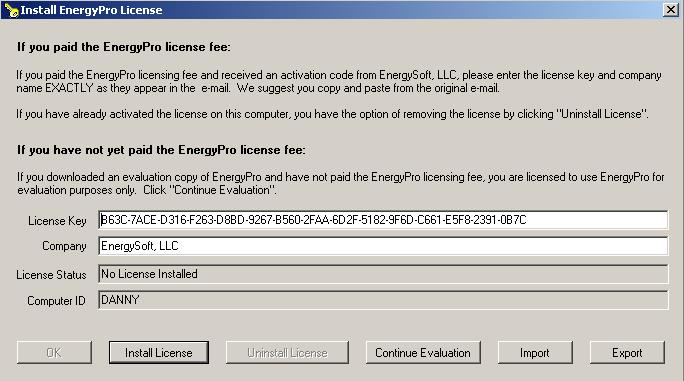
The first thing you need to do is follow the instructions in the email that was sent when you purchased the software regarding copying and pasting the company name and license key into the software activation window of EnergyPro. Once you have done this the license activation window should look like this, with your company name and license key:
When you hit the ‘Install License’ key it will come up with a message window that looks like:
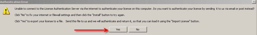
Click ‘Yes’
You will then see a screen like this:
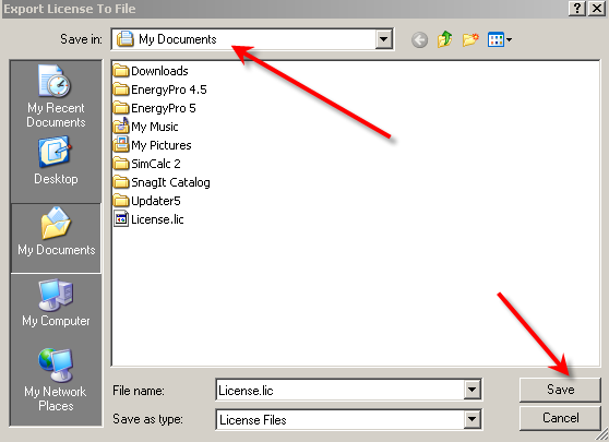
Click save and remember where it is saved to (in this case it is saved to My documents).
You then need to send that license.lic file in an email to sales@energysoft.com for them to authenticate it and send it back.
Once you have received the email with the authenticated license.lic file, you will need to save the file somewhere on your computer to be used later. You will not be able to open the license.lic file by double clicking on it.
Go into EnergyPro and open the software activation window by going to Help / software activation, it will look like:
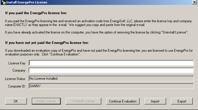
Click on the ‘Import’ button and in the ‘Look in’ section, go to where ever you have saved the AUTHENTICATED license.lic file that energysoft sent back to you. It should look like:
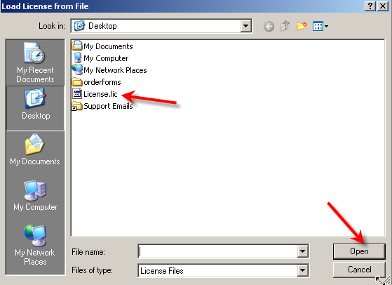
Click ‘Open’
You should see this screen:
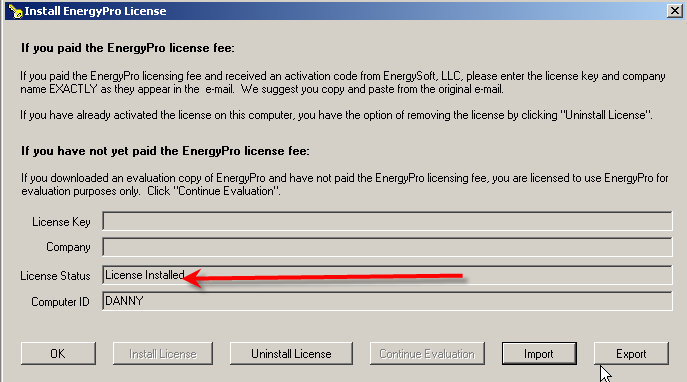
If you see ‘license installed’ then you have successfully installed the license. Go ahead and use the software.
This issue is related to your Windows scale and layout settings. To fix this, do the following:
Right mouse click on the desktop and select Display Settings.
Set “Scale and layout” to 100%
Begin by removing the license key from the old computer. This is done via Help | Software Activation. Select the option to “Uninstall License”. You can now uninstall EnergyPro from that computer via Windows Control Panel.
Once this is done, install EnergyPro on the new computer, select Help | Software Activation and enter the original activation information that sales sent via e-mail when you purchased the software. If you do not have the original e-mail, contact sales@energysoft.com to have the information resent.
In the subject line of the email that sales had provided that has the activation key it should indicate the version of EnergyPro the activation key applies to. You need to make sure you have downloaded the appropriate version of EnergyPro for your activation key. The error message occurs either when the company Name or License key is entered incorrectly, or that you have downloaded the wrong version for your license key.
If you do have the correct version of EnergyPro downloaded then make sure that when you copy the license key/company name that there are no leading nor trailing spaces at the beginning or end of both the Company Name and the Activation key when you paste it into the activation screen. It is vital that you COPY and PASTE both the license key and company name directly from the e-mail, failure to do so will result in the error message prompt.
If you still are experiencing difficulties after trying this please contact sales@energysoft.com for further assistance
2. General (21)
In the Central System library, begin by defining a System Type, generally it will be Split DX. Under the Heating Type select Dual Fuel Heat Pump.
Input the HSPF rating as well as the AFUE rating for the Heat Pump along with the heating capacities.
Inputs for this type of system are always done at the Plant level of the Building Tree in the DWH tab. Inputs depend upon the Occupancy you are working on.
Single Family: You will input the Solar Savings Fraction for the Solar System directly. This number will come from the Solar designer for the System.
Multifamily: You will input the specifications for the system including the specific Solar Panel Brand and Model, how many panels, as well as the solar storage tank specifics and the panel tilt and orientation. Note in this case you DO NOT get the option of inputting the Solar Savings Fraction, a fully designed system is required.
Nonresidential: There is no credit recognized in the Energy Code for this occupancy type.
At the top level of the Building Tree, in the PV+Batt tab, we offer the option to input a Battery Storage System, however there is one important restrictions on the use of this feature as follows:
- Battery storage and PV are only recognized for New Construction projects, not for Additions and/or Alterations.
When inputting the Battery system, you will need to indicate the size of the battery, as well as the strategy used to charge the battery. In most cases this will be the Basic charging selection. In addition, you will need to indicate the efficiency of the system used to charge the battery as well as to discharge the battery.
At the Zone level of the Building tree, under the selection for Building Story, you have added a Multiplier (2, 3 etc) to this entry which multiplies the entire Zone and everything in it.
To fix this, click on the Zone in the Building Tree, click the entry for Story and change the Number of Duplicate Stories to 1.
Navigate to the DHW/Boiler library and create a new Water Heater. Set the Water Heater Type to “Heat Pump”. Enter the Volume, Uniform Energy Factor and Input Rate from the manufacturer’s specifications. Note that sometimes the Uniform Energy Factor may be listed as the COP in the data.
For residential projects (single family, multifamily, hotel/motel), you may select a model that has been tested by the Northwest Energy Efficiency Alliance (NEEA) by clicking on the “Select NEEA HP” button on the dialog. Note that for NEEA rated models, the efficiency is not relevant since the NEEA selections contain performance curves specific to that model. Also, the list of water heaters shown is provided by the CEC, we have NO control over that listing. If you cannot find your model in that list, you can input the UEF and size rating for the unit.
Note that you cannot use a Tank Style Heat Pump Water Heater as the heating source for the home. In this circumstance, the CEC requires you to model this as Electric Heat. You cannot input the Heat Pump Water Heater as ANY source of hot water for either a Hydronic Heating System, nor for a Combined Hydronic Heating System. You will need to model this as electric heat.
As of EnergyPro v6, the energy budget for your building is set internally by the CEC supplied compliance engine (CBECC). As such, we do not have control or access to that feature so any questions on the energy budget should be directed to the CEC hotline at (800) 772-3300. The CEC publishes a document called the Alternative Calculation Method (ACM) manual, you can Google this and take a look at this document. Also, some of the training classes on the code will give you insight into that, and in the case of the Residential buildings, the Prescriptive Packages in Standards Section 150.1 would be your starting point. For Nonresidential lighting and envelope, the Prescriptive section of the Standards would also be a good starting point, but the HVAC is detailed in the ACM manual. Look in the EnergyPro Help for some information on those tables also.
You can edit the specs on an existing system or assembly from the libraries in EnergyPro or you can use the “Add new” button to create your own.
1. The EnergyPro libraries come pre-populated with most of the common utility rates in California.
2. Select an electric/gas utility rate at the Building level of the Tree, Utility tab. Note when selecting one you can use the green Import button to pick from a list.
3. Go to Calculations and check the box for the particular calculations you wish to run.
4. Calculate.
5. In the Report Wizard, Select the report labeled “ECON-1”, and proceed to finish.
6. Click the Print Preview button.
Under Help | EnergyPro News, we have a news feed that will alert you automatically to any new updates published for the software.
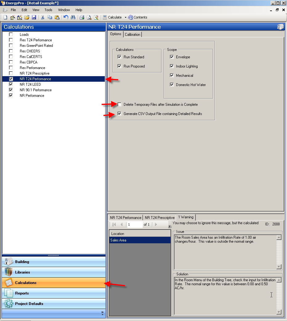
To create hourly output files in a CSV format (readable by Excel), you need to go to the calculations button on the bottom left, and then select whichever calculation you are working on (Residential Title 24 Performance, NR Title 24 Performance, NR ASHRAE 90.1, etc.) in the list above. Deselect ‘Delete Temporary Files after Simulation is Complete’ and then select ‘Generate CSV Output File Containing Detailed Results’ as shown in the screenshot below. Now run the calculations and the CSV file will be found in the Results folder located under “Documents/ EnergyPro 10/ Results”. See screenshot below.
The best way to create your own utility rate is to edit one of the utility rates that are already in the list. You will have to get the information from the utility company on their actual costs.
We recommend that you select the closest city, in the same Climate Zone as your location. As a general rule, you will find a location within a few miles in our list.
Inputs for PV are handled at the Top level of the Building Tree, in the PV+Batt tab.
In New Construction, Title 24 recognizes (and generally requires in order to comply) your inputs for PV, however in no case does the credit get recognized in additions and alterations. You have several options on how the PV is sized:
One approach is the Specify your PV Size. When using this option, you will input the specifics of your PV in the table at the bottom. This is the ONLY option for Multifamily and Nonresidential occupancies.
(The following options do not apply to Multifamily and Nonresidential occupancies)
Another option is to select a Standard Size PV system. Using this option, EnergyPro will size your PV system pretty close to what is used in the Budget.
A third option is to Maximize the PV size. EnergyPro will size the PV system as large as possible.
Note that several Title 24 based exceptions are available related to PV in this tab. Please see the Energy Code for more info,
Click on the red “X” to the left of the entry. Select Yes when asked to confirm the deletion. Your input will show Undefined. (Note: this operation will not delete the item from the library.)
When a new window is created in EnergyPro it is created specific to your file, meaning that the item will only appear in the file being modified. Once inside the Fenestration Library select the window that you have customized and click on the Export button. The program will ask you to select a destination, by selecting the Default Library and mouse clicking the OK option, the window you have created will now be added to the Default Library. Any new projects that you start will automatically include the contents of the Default Library. However, the window you just created will not appear in an other projects that have already been created.
This window can be exported to an older project by exporting from the default library to the older project file. The default libraries can be accessed under Tools | Default Libraries.
You will have to input an interior window as an interior door in an interior surface (wall).
A user may combine systems or any input for that matter that are identical and whose requirements do not mandate that detailed inputs be used. When combining inputs, be sure to keep track of the multipliers and that your floor levels are being reported correctly. The criteria in this case would be that the systems serve zones that are thermally identical. An example of this would be a core zone of a building. Five different orientations would not meet this criteria. Consult the CEC’s Residential and Nonresidential Manual for information on the depth of detailed information that may be required for the situation in question.
EnergyPro requires that you input your heat pump heating capacity at the AHRI rating condition of 47 degrees F dry-bulb. Typically, design conditions at your actual site are much colder, so EnergyPro will de-rate the heat pump capacity, based upon this condition.
EnergyPro requires that you input your air conditioner cooling capacity at the AHRI rating condition of 95 degrees F dry-bulb outside air, 67 degrees F wet-bulb entering air. Typically, design conditions for your building will be different. Changes in outside design conditions and indoor entering air conditions will result in a different overall capacity for your system than the value you specified in the library.
The latest version of EnergyPro can read version 8 and newer files. Files from V7 and older should be loaded and saved in version 8 then read into the newest version.
3. CF1R/LMCC Registration (11)
We have detailed instructions here on how to register your CF1R/LMCC Forms
When you register a project with EnergyPro you will be prompted to “Save As” during the registration process. It is up to you to select where you would like to save the .XML file in order to locate it when it is time to upload the file to the appropriate ECC provider to complete the registration process. It is easiest to save to file to your desktop.
* If you cannot remember where you chose to save the .XML file, you will have to go through the registration process again. Credits for re-registrations can be obtained by emailing support@regt24.com
In cases where the Certificate requires ECC rater verification in the field for certain measures, the form will include a watermark. This means that the Certificate of Compliance data must be registered with an ECC provider. You will need to establish an account with them and upload the data file for your project. Then, they will issue a registered version of the form that does not include the watermark.
As long as the BLD file is saved AFTER you register it, the software will recognize that this is a re-registration and will notify you that you will not be charged.
If the software does notify you that you will be charged again, that means you have made changes to the Project Title (Name/Address), or to the registration name or plan name. This is treated as a new project and the software will charge for that. You may contact us for a credit.
Credit for duplicate registrations will require you to submit both the old and the new XML file for review to support@regt24.com, and credit given at their discretion. Before you request this, confirm in the Activity tab that is shows the duplicate charge.
EnergySoft will charge you $7 to register the form. This will be subtracted from your account balance automatically.
The ECC provider website will give you the ability to put your signature on the Form automatically when you setup your account. The Project Designer will still need to place their signature via the ECC provider website. You can get more information on this process at the ECC provider website.
Once you register a project your account will be debited the registration fee. We cannot do anything for you at that point. Please do not call us and request a refund as we have no way to process it, nor is it worth your time or ours to deal with such a small fee. The software will warn you before it charges your account, so you have the ability to say no at that point.
Under Tools | CF-1R registrations, there is a tab that will allow you to add funds. Note that all payment processing is handled by PayPal and we collect no credit card information. You do not need a PayPal account with this option. Another option is to send a check to us, and we can add funds to your account, but this will take a few days.
Your EnergySoft account is tied to your EnergyPro user number, so your office will have one account with us for the purposes of funds. You can have as many people in your office that have a licensed version of EnergyPro registering projects using that account. Fees will come out of your account with EnergySoft each time a project is registered. As far as the ECC provider account, you can choose to have individual accounts for each person in your office on each computer, or a single account. That is your choice, you decide what works best.
You will need to re-register the project from within EnergyPro, and then re-upload the file to the ECC Provider website.
Under Tools | CF-1R registrations, there is a tab that will show you all account activity related to your EnergySoft account.
4. Single Family Title 24 (41)
This would require us to review a detailed set of plans and specifications for the project. Our software support services are confined to issues related to running the software, not how to design a building to be in compliance so this is not something you should contact us about. However, we do realize the new codes are much tougher so we have compiled some ideas below for you to consider.
- High Performance Attics
- High Performance Walls
- Quality Insulation Installation
- In Cooling Climates, Windows with a lower SHGC.
- In Heating Climates (Zones 1, 3, 5, 16) Windows with a higher SHGC will help matters.
- Windows with a lower U-Factor
- Reductions in your Window and or Skylight area (remember, 20% is the limit)
- Attic Radiant Barriers
- Cool Roofs
- Whole House Fans
- R-8 Duct Insulation
- High Efficiency Furnace (94%+)
- High Efficiency Air Conditioner (15 SEER+)
- High Efficiency Heat Pumps
- Refrigerant Charge Verification
- Verified Low watt/cfm fans
- Verified High cfm/ton air system designs
- Ducts and Air Handlers in Conditioned Space
- Energy or Heat Recovery Ventilators
- Heat Pump Water Heater (once again, this will help with the emissions score)
- NO Electric Resistance Water Heating
- More efficient Fans and Variable Air Volume Systems (Non-residential)
- Photovoltaic (PV) Solar System
- Solar Thermal Domestic Hot Water System
- Battery Storage Systems
In addition, getting a better idea of what the Standard Building looks like so you will understand the budget would be a good idea. There are a lot of online resources to help you understand the energy code including trainings offered by the utilities.
Starting in EnergyPro 10.0 you will find two LSC (Longterm System Cost) scores and a Source (emissions) score when doing a compliance calculation. An LSCe score which represents the efficiency of the building design and includes all end uses with the exception of PV. An LSCt score which is the building efficiency score including the savings contribution of the PV system, and a Source score, an emissions score that is similar to the LSCt score and includes all end uses and factors in the Green House Gas emissions that result from the gas and electricity that is consumed to run the building. In the case of buildings with gas appliances, you can expect your proposed Source emissions score to be high. Starting with the 2025 Energy Code, New Construction projects are required to comply with all three scores.
Note also that Single Family New Construction projects are also subject to the Peak Cooling limitation that is shown onscreen and must comply with that fourth compliance metric which represents the peak hour cooling consumption in kWh.
All Additions and Alterations are only required to comply with the LSCe score.
This exception in the code allows any dwellings or additions that are 500 or less to use an Electric water heater. Three things need to be designated:
- The area of all New square footage must be 500 sqft or less.
- The water heater must be designated as Electric Resistance.
- At the plant level of the Tree, in the DHW tab, you must specify the Distribution as Point Of Use (POU)
Our example file, Single Family EA+ADU.bld provides an example of this.
Note the POU credit requires the design of the water heating system meets the criteria in 5.6.2.3 of the Single-Family Manual, including the following hot water pipe length limitations from the water heater to the fixtures:
3/8” pipe – 15 ft
1/2” pipe – 10 ft
3/4” pipe – 5 ft
For 2025, the CEC has added a new compliance metric, the Peak Cooling score that expresses peak cooling consumption of the home in kWh. This metric only applies to New Construction homes, and not to additions and alterations. Projects in Climate Zones 4 and 8-15 are subject to this new metric.
What does it include? All electricity consumption of the home during the Peak Summer hour.
What can I do to reduce my score? Window SHGC and U-Factor improvements, Insulation, Duct Insulation and Location, AC efficiency, and using a Whole House Fan will all lower this number.
What will not affect the score? Batteries, PV, Lighting, Receptacle will have no impact.
Is this a bug in EnergyPro? No, the CBECC software applies the same restrictions.
As an important note, our own projects are struggling with this score, and we in fact have projects that WILL NOT comply that are perfectly reasonable projects. The CEC has been altered to this problem, and we expect some movement in this regard from them as we ramp up for the new code. In the meantime, we recommend you contact the Hotline on specific projects you have that are struggling. The contact e-mail is: Title24@energy.ca.gov
You must consider a Heat Pump as the source of heating, using electric resistance heat is not going to comply. For the Domestic Hot Water, an electric resistance unit (either tank style or tankless is not going to comply). Try it if you do not believe us, you will need to consider a Heat Pump Water Heater. The good news is that starting with the 2019 code, your Heat Pump heater is compared with a Heat Pump Space Heater in the Standard, same goes for the Heat Pump Water Heater, so any penalty you might have on achieving compliance is related to the design of the rest of the home. See here for further tips.
When modeling an ADU, there are several circumstances to consider.
In the case of an attached Garage conversion, this is considered an Addition, and the floor space of the Garage is input as New at the Zone (no it is not an Alteration). See our example file Single Family EA+ADU.bld for an example. Note in this case, the code does allow for the “Existing Wall w/Siding” exception to be used, listed under the wall input.
In the case where they are adding square footage to an existing home, it is treated the same as the Garage conversion (New at Zone), and you may be able to claim the “Wall Extension” exception, also given under the wall input.
In the case of a renovation of an existing building on the property (garage, shed), this is also an Addition (New at Zone) as described above, and also qualifies for the “Existing Wall w/Siding” provided the siding remains. Also, any type of Addition to this same structure is still treated as an Addition to the main house. You can decide to treat this as Addition Alone or E+A+A. Existing Floor area, where required, should be for the main house.
In the case of a New building on the site, this is now input as New at both the Zone and the Top level of the Tree, and the ADU designation at the Zone has no relevance. It is now treated as a new home, and will be documented as such, and the output will not indicate ADU. This circumstance will also require a PV system be installed, either on the main home or the ADU. Note an expansion of the existing PV system is an acceptable way to meet this requirement, but you cannot count the existing PV system as having met the requirement.
In ALL cases, an ADU will require an IAQ fan, verified in the field by an ECC rater.
At the System level of the Building Tree, create a new Central System in the library. The system type should be set to Air to Water Heat Pump. Enter the Heating Capacity and COP in the Heating Tab, and the Cooling Capacity and EER in the Cooling Tab.
If the AWHP also supplies the Domestic Hot Water you should indicate as such when defining the AWHP and at the Plant level of the Building Tree, Domestic Hot Water tab, do not input a water heater.
We have two examples of this system in the Single Family AWHP.bld and the Multifamily AWHP.bld example files.
If you wish to make this a ground coupled system (geothermal), check the box for Ground Coupled when defining the system.
An unventilated attic (sometimes referred to as a sealed attic) is created in the Assembly Editor by first importing an Attic assembly with R-0 insulation using the green Import button. At the Res T24 Performance tab, check the box for Unventilated. Now input whatever level of insulation you have at the rafters under the Below Roof Deck entry.
Note if using this assembly for Prescriptive compliance, the entry in the JA4 tab for Interior Insulation should be included.
When using QII, the CBECC Res engine requires any surfaces (walls, roofs, floors) be selected as different construction assemblies between the existing part of the house or the garage, and the new surfaces. Thus if you had an R-19 Wall selected for the new part of the home, your Garage and/or Existing part of the home would need to use a different wall, for instance “R-19 Existing” or whatever other unique name you wish to assign. So you cannot use the exact same assembly names in the library in these cases.
The only time you can consider the ducts as being in conditioned space is if the ducts and air handler are installed underneath the ceiling inside the thermal and air barrier of the envelope.
If the ducts are in an attic with continuous insulation at the roof deck is that considered conditioned space? No, however, when there is roof deck insulation the attic temperature will be much closer to the conditions within the conditioned space and that is already accounted for in the software. So there is a tremendous benefit from roof deck insulation even if the ducts are not able to be considered as within conditioned space. (NOTE: Because a radiant barrier requires a 1-1/2″ air space, when roof deck insulation is modeled uncheck the radiant barrier option.)
In the Construction Assembly editor at the General tab, we provide a pulldown that lists all available Roofing Types that the CEC provides. The CEC has a limited list and would need to expand that list in CBECC, we have no control over it, so if you do not see your roofing material, you must choose the closest option provided. You CANNOT use the layers tab for Residential projects.
In the Construction Assembly editor, at the Residential T24 Performance tab, we provide a pulldown listing all Exterior Wall Finishes at the bottom that the CEC provides. The CEC would need to expand that list since we have no control over it, so if you do not see your exterior wall material, choose the closest option provided.
Section 150.2 of the code specifically allows small additions that comply Prescriptively to be built with either 2×4 R-15 or 2×6 R-19 walls in cases where that wall is an extension of the existing wall, or the siding is not being removed. You are responsible for demonstrating that the wall is in fact an extension per this section, or has the siding remaining so we recommend discussing this with the CEC Hotline (800) 772-3300.
Assuming you do meet the exception, we have a pulldown that allows you to indicate that exception at the Wall level of the building tree. This exception will then be documented on the CF1R.
Select an Attic roof assembly that has the appropriate level of ceiling insulation in the EnergyPro Assembly library. For a high performance attic with above deck insulation edit the input for “Above Deck Insulation” (or if doing Prescriptive compliance “Exterior Insulation”) and put in an R-Value for the insulation. For a high performance attic with below deck insulation edit the input for “Below Deck Insulation” (or if doing Prescriptive compliance “Interior Insulation”) and put in an R-Value for the Insulation.
If you do the below deck approach, you should not include a radiant barrier since the insulation will be up against the barrier and will negate the product effectiveness.
In the assembly editor, you will add Exterior Insulation to your wall assembly. If the project is Nonresidential Performance, this will be done in the Layers tab by clicking on the Yellow Plus sign to add a layer. Double click on the layer and select an insulation material from the material list, then move it so it is on the exterior of the wall framing.
If the type of project is Prescriptive, then edit the JA4 tab and simply type in the R-Value of the insulation in the Exterior Insulation entry. If the project is a Residential Title 24 Performance project, enter the Exterior Insulation on the Res T24 Performance tab.
At the top level of the Building Tree, in the Misc tab, you can select from a variety of different ventilation cooling systems, including a Whole House Fan. Once the type of ventilation cooling system is selected, at the System level of the Building Tree, in the Residential tab, input the total CFM for your fan, along with the total wattage. Note that the CEC maintains a list of approved whole house fans with specifications on their website.
Select the Assembly Library by clicking on the Libraries in the bottom left corner and selecting the library in the list that appears above. Now in the right pane, select your roof assembly. Check the box that indicates the roofing is CRRC-1 certified, then enter your roof reflectance and emittance. This data will come from your roof properties, typically obtained from the Cool Roof Rating Council website.
Quality Insulation Installation (QII) is indicated at the top level of the Building Tree, in the Residential tab by checking off the box. Note that while you will get substantial credit for this feature, it is an option you should verify with the builder.
EnergyPro is “ZNE Ready” meaning it is now configured to allow you to demonstrate a residential building meets the ZNE definition the CEC describes on the CF1R document. To help you understand this we have provided a new example BLD file designed to run in EnergyPro that shows an Energy Score at or below Zero. In addition, the new version provides reporting that will help you and your client understand the energy usage in the home. Please look at the pages on the sample report, in particular the last two pages. The software includes a full hourly annual solar system simulation based upon the CECPV/PVWatts simulations. Look at the example file at the top level of the Building Tree, PV tab.
For residential projects starting in the 2025 code, the standard water heater is a NEEA Heat Pump water heater in both the Prescriptive and Performance compliance approaches so using any gas fired unit with a tank, and especially an electric resistance water heater will produce a significant penalty.
For commercial projects, the standard water heater under Performance varies by occupancy type. However, under Prescriptive, you are allowed to use an electric water heater. Our recommendation is to submit the DHW using the NRCC-PLB-E form which is available under the NR T24 Prescriptive forms list.
Under the Calculation Options, bottom left button, click and you will see the NR T24 Performance calculations in the list above. Select this, then on the right unclick DHW from the scope and then rerun and the penalty will be gone.
A duplex is treated as single family, as is a townhome or townhouse, not as multifamily. You must show compliance based upon each dwelling unit so a model for each unit must be developed, with separate reports. Any surfaces between the units should be modeled as Interior surfaces, just do not enter the “Adjacent To” setting for the space it is next to so you can avoid entering that other space.
They are just warnings, if you feel your inputs are set properly then it is fine to ignore them. EnergyPro sets standards for these inputs and gives you a warning if anything is more than 30% outside of that range.
The CF-1R is required on the plans, we also recommend the Mandatory Measures form.
The amount of credit for an alteration depends on whether an ECC rater verifies the existing conditions. For example, if you are altering existing metal frame, single-pane windows to vinyl frame, low-e windows, if you do not check “ECC Verification” at the top level of the Building Tree, Misc Tab, the software will not prompt you to input the Existing Conditions. You will only input the efficiency of the new windows and your credit is based on the difference between the new window U-factor/SHGC and 0.40/0.35 (values from Table 150.2-B of the Standards). If you check “ECC Verification” and enter the existing conditions of 1.28 U-factor/0.80 SHGC, the credit you receive is based on the difference between these values and the U-factor/SHGC of the new windows.
You can let this default and it will be modeled automatically for you.
If you wish to specify a fan, go to the Top level of the Building Tree, Residential Tab, and check the box to indicate you want a Non-Default IAQ fan.
Now you can input the IAQ fan specifics at the Zone level of the Building Tree, Dwelling Units Tab.
A wall facing a garage is input as an interior wall, and thus the program will register no solar gain.
At the System level of the Building Tree, Residential tab, simply check the Wood Stove checkbox. This applies to any type of wood fired appliance used to supply heat.
When inputting these systems, each Indoor unit should be input at the System level of the Tree as its own System using the Outdoor unit Efficiencies, feeding the corresponding Zones. and at the System Distribution tab, the unit should be identified as Mini-Split, Multi-Split or VRF, to ensure correct reporting.
There is no set limit to the length of names in the building tree, but CBECC adds data to the field names to keep track of the parent/child relationships and interactions. So you might want to try limiting names to 25 characters.
Only fixed Overhangs and Side Fins are recognized in the modeling tools, the CEC does not currently recognize other devices such as shade screens or blinds.
The calculation engines in EnergyPro that are now used for Title 24 code compliance are developed and maintained by the California Energy Commission. The new Residential and Nonresidential calculation engines they provide are significantly slower than the prior ResSim and DOE-2 engines we provided in older versions of EnergyPro. The new engines incorporate CSE and EnergyPlus, which are more powerful than the older calculations, and simulate the zones much more thoroughly, resulting in longer simulation runtimes.
Try to keep the number of zones in your model to an absolute minimum, but it is not unusual to see run times of over an hour on more complex models.
To speed up run times, you can select the Quick Analysis option, which will run a partial year simulation. In the bottom left, click on the Calculations. In the list that appears above, select either Res T24 Performance or NR T24 Performance. On the right will appear the option for Quick Analysis. This will cut your runtime in half. However that option will trigger a report that includes a watermark that states “Not useable for compliance” since you must run the full year for code compliance.
Another option is to check the box for “Do Not Generate PRF01/CF1R” This will skip the report generation feature that occurs at the end and can save additional time, but you will not get the Title 24 reports needed for permitting.
To model a Gas Boiler with Radiant Floor Heating, start at the Central System Library.
At the Heating Tab:
System Type: Split DX
Heat Type: Hot Water (Will use efficiency from boiler)
Heating Output: Output of System
Cooling tab: enter relative cooling information, or Zero for output if there is no cooling (See the topic on No Cooling)
Fans Tab: 0 cfm, 0 hp
At the System Level of the Building Tree:
General Tab:
Select the Central System entry created above.
Hydronic Space Heating: Choose DHW or Boiler provide heat. Note this will point the program to either the DHW or the Heating Hot Water tab at the Plant level of the tree for the source of heat.
Distribution Tab:
Heating Distribution: Radiant Floor
Select a heated slab-on-grade from the library at the Slab element.
Notes:
If the same boiler is used for radiant floors and domestic hot water, model the boiler in the DHW tab and at the System level of the tree select ‘DHW boiler provides heat’.
Sample file located in My Documents\EnergyPro x\Projects\Single Family Combined Hydronic.bld
It may be the case that there is a dedicated boiler for radiant heat. In this case, model that boiler in the Boiler tab and in the Residential tab select ‘Heating boiler provides heat’. Then model the Domestic hot water (used for sinks, showers) in the DHW tab.
A sample file is located in My Documents\EnergyPro X\Projects\Single Family Separate DHW & Hydro.bld
Below is a list of tabs in which you need to enter information for a residential title 24 calculation. You will not need to enter every available input in each tab.
Building icon:
![]()
Project Design Data, Project Title, Designer, PV+Batt
Plant Icon:
![]()
Heating Hot Water (if you have a boiler for space heating which is separate from the domestic hot water heater), Domestic Hot Water
System Icon:
![]()
General, Distribution, Residential, ECC Credits (if you are taking ECC Credits)
Zone Icon:
![]()
General
Room Icon:
![]()
General
Within the Room icon, you will enter building assemblies such as Roofs, Walls and floors by right clicking on the room icon and selecting Add / …
You do not need to model lighting in a residential title 24 calculation.
In the Central System Library, create a new system. Set the System Type to SplitDX. Now, set the heating type to Electric Resistance.
Prescriptive measures are the values included in the Code take from the Prescriptive Package in that climate zone – it is also used as the design of the baseline or Standard building; mandatory measures have to be meet no matter what. For example if a building complies using the performance approach, with R-7 insulation in a raised floor, but R-19 must be installed, then the mandatory minimum is required.
Interior surfaces are surfaces between two spaces and can be either walls, ceilings or floors. Note that interior walls can also contain doors. If you have an interior window, treat it as an interior door in an interior wall. Insert an interior surface in the room and set it adjacent to the other room. If you do not set it adjacent to another room, or you set it adjacent to itself, it is treated as adiabatic.
Depending upon the occupancy, EnergyPro offers two possible scenarios for modeling this type of device as follows:
Nonresidential Occupancies that use ducted HVAC systems in EnergyPro that are not Zonal (FPFC, PTAC, WSHP, VRF) have Exhaust Air Heat Recovery ERV or Heat Recovery Ventilator HRV as an option on the HVAC system. See the Outside Air tab in the Central System Library for these input options.
Residential occupancies have the option also. Start by going to the Top level of the Building Tree, Misc tab and specifying a non-default IAQ fan. Now at the Zone level of the Building Tree, Dwelling Units tab you can configure the IAQ fan as a balanced ventilation system with the option of specifying the heat recovery efficiency.
For Title-24 compliance purposes, the CEC requires cooling to be included in the proposed building model. When modeling a single family project, the software will include a default cooling system when calculating the results. This system is defined automatically and you have no option to change the definition of the system. When modeling a nonresidential project, you are responsible to define the default cooling system for your project, you cannot leave it undefined. This would be a code minimum efficiency cooling system included as part of your model.
If you find your cooling numbers are causing the building not to comply, review your window inputs and in particular the SHGC since that will affect the cooling usage of the default system.
No, the standard building is a fixed entity based upon Title 24 guidelines, and the CEC does not permit you to change this. To see the building comparison that Title 24 uses in the standard design, look at the Residential and Nonresidential Alternative Calculation Method Manuals.
Because the PRF-01 and CF-1R reports are created through an online based report generator on the CEC website, you will have to have an Internet connection in order to generate any Certificates of Compliance. Assuming you have Internet, you might check with your IT department to see if your system blocks the report generator from being accessed. You also have the option of turning off the reports, this option is found by clicking on the bottom left “Calculations” and then in the list above selecting the appropriate calculation. The display on the right will show the option to turn off the reports. You will eventually have to uncheck tis option and rerun the calculations to get the final Certificate of Compliance.
If you select the Calculation option on the bottom left side of the screen, then select the T24 Performance calculation (either Res or NR) in the list that appears above this selection, you will see an option to “View CBECC Log”. If you click on this button, you will see the CEC log file reporting the results of the simulation. Note that this file will not exist unless you first uncheck the option for “Delete Temporary Files”, then click on calculate to run the simulation. At the end of the simulation you can view this log file and see what problems you have.
5. Multifamily Title 24 (5)
Starting in EnergyPro 10.0 you will find two LSC (Longterm System Cost) scores and a Source (emissions) score when doing a compliance calculation. An LSCe score which represents the efficiency of the building design and includes all end uses with the exception of PV. An LSCt score which is the building efficiency score including the savings contribution of the PV system, and a Source score, an emissions score that is similar to the LSCt score and includes all end uses and factors in the Green House Gas emissions that result from the gas and electricity that is consumed to run the building. In the case of buildings with gas appliances, you can expect your proposed Source emissions score to be high. Starting with the 2025 Energy Code, New Construction projects are required to comply with all three scores.
Note also that Single Family New Construction projects are also subject to the Peak Cooling limitation that is shown onscreen and must comply with that fourth compliance metric which represents the peak hour cooling consumption in kWh.
All Additions and Alterations are only required to comply with the LSCe score.
You can review two sample files we provide, the Multifamily Example.bld, we also provide a file Multfamily Electric.bld Both are modeled at the Plant level of the tree, Domestic Hot Water tab. Note this topic is ONLY applicable to Multifamily and Hotel/Motel guest room applications. The CHPWH cannot serve other zone occupancies.
The inputs for the CHPWH are under Central HPWH and your choices include the following:
- Residential NEEA rated Product – This would be a series of smaller scale tank style Water Heaters ganged together to meet the DHW needs.
- Commerical Product – This would be a larger Tank style unit that has commercial ratings. Currently the only choice in this product offering is the AO Smith 120 gal.
- Single Pass Primary – This is a large instantaneous commercial single pass heat pump that will be combined with external storage tanks specified on the dialog.
- Muti Pass Primary – This is a large instantaneous commercial multi pass heat pump that will be combined with external storage tanks specified on the dialog. (note this choice will generally invoke a penalty, as the more efficient single pass system is used in the standard building)
Note when selecting from the list of models, we have NO control over that list, as they are provided by the CEC, if you do not find your model, you can use one from the end of the list marked as Generic
A system can optionally have a secondary loop provided, the configuration of the secondary loop is specified further down with the same options above, plus an option for an electric resistance storage tank. The piping arrangement can be plumbed as parallel or series.
When the CHPWH option is checked, the water heater input at the top of the screen on the DHW tab is used to supply Nonresidential spaces, if the CHPWH feeds these spaces, we suggest that you create a dummy electric WH if necessary.
At the System level of the Building Tree, create a new Central System in the library. The system type should be set to Air to Water Heat Pump. Enter the Heating Capacity and COP in the Heating Tab, and the Cooling Capacity and EER in the Cooling Tab.
If the AWHP also supplies the Domestic Hot Water you should indicate as such when defining the AWHP and at the Plant level of the Building Tree, Domestic Hot Water tab, do not input a water heater.
We have two examples of this system in the Single Family AWHP.bld and the Multifamily AWHP.bld example files.
If you wish to make this a ground coupled system (geothermal), check the box for Ground Coupled when defining the system.
When inputting these systems, each Indoor unit should be input at the System level of the Tree as its own System using the Outdoor unit Efficiencies, feeding the corresponding Zones. and at the System Distribution tab, the unit should be identified as Mini-Split, Multi-Split or VRF, to ensure correct reporting.
These occupancies are listed as exempt lighting under Section 140.6 of the code, and as such the lighting does not appear on the reports, nor does it affect any calculated results. Basically the lighting is subject to mandatory measures, but the quantity of lighting is unregulated and thus not reported.
6. Nonresidential Title 24 (16)
This would require us to review a detailed set of plans and specifications for the project. Our software support services are confined to issues related to running the software, not how to design a building to be in compliance so this is not something you should contact us about. However, we do realize the new codes are much tougher so we have compiled some ideas below for you to consider.
- High Performance Attics
- High Performance Walls
- Quality Insulation Installation
- In Cooling Climates, Windows with a lower SHGC.
- In Heating Climates (Zones 1, 3, 5, 16) Windows with a higher SHGC will help matters.
- Windows with a lower U-Factor
- Reductions in your Window and or Skylight area (remember, 20% is the limit)
- Attic Radiant Barriers
- Cool Roofs
- Whole House Fans
- R-8 Duct Insulation
- High Efficiency Furnace (94%+)
- High Efficiency Air Conditioner (15 SEER+)
- High Efficiency Heat Pumps
- Refrigerant Charge Verification
- Verified Low watt/cfm fans
- Verified High cfm/ton air system designs
- Ducts and Air Handlers in Conditioned Space
- Energy or Heat Recovery Ventilators
- Heat Pump Water Heater (once again, this will help with the emissions score)
- NO Electric Resistance Water Heating
- More efficient Fans and Variable Air Volume Systems (Non-residential)
- Photovoltaic (PV) Solar System
- Solar Thermal Domestic Hot Water System
- Battery Storage Systems
In addition, getting a better idea of what the Standard Building looks like so you will understand the budget would be a good idea. There are a lot of online resources to help you understand the energy code including trainings offered by the utilities.
Yes, unlike the older forms, the new forms have sections at the beginning that confirm if the building complies based upon the information you have input. You will generally find a section related to the Controls, as well as related to other aspects such as the installed wattage, etc.
It is important to make sure all relevant sections of the form are completed, and make sure you have input any Mandatory controls. These are input at the Top level of the Tree, Forms tab. In particular, any options selected here that have an asterisk (eg lighting control options) must include a valid explanation of the reason for the exemption.
Select the Assembly Library by clicking on the Libraries in the bottom left corner and selecting the library in the list that appears above. Now in the right pane, select your roof assembly. Check the box that indicates the roofing is CRRC-1 certified, then enter your roof reflectance and emittance. This data will come from your roof properties, typically obtained from the Cool Roof Rating Council website.
They are just warnings, if you feel your inputs are set properly then it is fine to ignore them. EnergyPro sets standards for these inputs and gives you a warning if anything is more than 30% outside of that range.
There is no set limit to the length of names in the building tree, but CBECC adds data to the field names to keep track of the parent/child relationships and interactions. So you might want to try limiting names to 25 characters.
Only fixed Overhangs and Side Fins are recognized in the modeling tools, the CEC does not currently recognize other devices such as shade screens or blinds.
The calculation engines in EnergyPro that are now used for Title 24 code compliance are developed and maintained by the California Energy Commission. The new Residential and Nonresidential calculation engines they provide are significantly slower than the prior ResSim and DOE-2 engines we provided in older versions of EnergyPro. The new engines incorporate CSE and EnergyPlus, which are more powerful than the older calculations, and simulate the zones much more thoroughly, resulting in longer simulation runtimes.
Try to keep the number of zones in your model to an absolute minimum, but it is not unusual to see run times of over an hour on more complex models.
To speed up run times, you can select the Quick Analysis option, which will run a partial year simulation. In the bottom left, click on the Calculations. In the list that appears above, select either Res T24 Performance or NR T24 Performance. On the right will appear the option for Quick Analysis. This will cut your runtime in half. However that option will trigger a report that includes a watermark that states “Not useable for compliance” since you must run the full year for code compliance.
Another option is to check the box for “Do Not Generate PRF01/CF1R” This will skip the report generation feature that occurs at the end and can save additional time, but you will not get the Title 24 reports needed for permitting.
Prescriptive measures are the values included in the Code take from the Prescriptive Package in that climate zone – it is also used as the design of the baseline or Standard building; mandatory measures have to be meet no matter what. For example if a building complies using the performance approach, with R-7 insulation in a raised floor, but R-19 must be installed, then the mandatory minimum is required.
Interior surfaces are surfaces between two spaces and can be either walls, ceilings or floors. Note that interior walls can also contain doors. If you have an interior window, treat it as an interior door in an interior wall. Insert an interior surface in the room and set it adjacent to the other room. If you do not set it adjacent to another room, or you set it adjacent to itself, it is treated as adiabatic.
For Title-24 compliance purposes, the CEC requires cooling to be included in the proposed building model. When modeling a single family project, the software will include a default cooling system when calculating the results. This system is defined automatically and you have no option to change the definition of the system. When modeling a nonresidential project, you are responsible to define the default cooling system for your project, you cannot leave it undefined. This would be a code minimum efficiency cooling system included as part of your model.
If you find your cooling numbers are causing the building not to comply, review your window inputs and in particular the SHGC since that will affect the cooling usage of the default system.
No, the standard building is a fixed entity based upon Title 24 guidelines, and the CEC does not permit you to change this. To see the building comparison that Title 24 uses in the standard design, look at the Residential and Nonresidential Alternative Calculation Method Manuals.
The baseline building is a Packaged DX system in this case. This system may not have pumps and has no cooling tower, so the reported energy will be zero. This is a standard comparison that is dictated by the code you are comparing to and the software cannot change what the budget building looks like.
All nonresidential forms are certificates of compliance and should go on the plans.
Below is a list of tabs in which you need to enter information for a non-residential title 24 calculation. You will not need to enter every available input in each tab.
Building icon:
![]()
Project Design Data, Project Title, Designer, Lighting Designer (if lighting is part of your scope), Mechanical Designer (if Mechanical is part of your scope), Outdoor (if outdoor lighting is in your scope)
Plant Icon:
![]()
Heating Hot Water (if you have a boiler for space heating which is separate from the domestic hot water heater), Chiller Water (if you have a built up HVAC system with a chiller) Hydronic (if you have a ground coupled system) Domestic Hot Water (unless DHW is not in the scope), Renewables (if there is a solar hot water heater you would model it here, you can ignore the Solar Space Heating and electricity production inputs)
System Icon:
![]()
General, Distribution, MCH-2 (if your model includes MCH-2 features)
Zone Icon:
![]()
General, Lighting, Mechanical (if you have zonal mechanical boxes or wish to adjust the ventilation)
Room Icon:
![]()
General, Infiltration, Occupant, Receptacle/Process, exhaust fan, lighting (if you are taking task or daylighting credits).
Within the Room icon, you will enter building assemblies such as Roofs, Walls and floors by right clicking on the room icon and selecting Add …
If you select the Calculation option on the bottom left side of the screen, then select the T24 Performance calculation (either Res or NR) in the list that appears above this selection, you will see an option to “View CBECC Log”. If you click on this button, you will see the CEC log file reporting the results of the simulation. Note that this file will not exist unless you first uncheck the option for “Delete Temporary Files”, then click on calculate to run the simulation. At the end of the simulation you can view this log file and see what problems you have.
7. Nonresidential Lighting (4)
Navigate to the top level of the Building Tree and select the Forms tab. In this tab you will find an LTI and an LTO selection. These will allow you to input any mandatory lighting controls that are needed for the report (hit the yellow Plus sign to add a control). Based upon the controls selected, all of the mandatory sections will be taken care of on these reports.
Note we provide a sample file (My Documents\EnergyPro x\Projects\Nonres Sample.bld) that demonstrates a complete example of these controls, as well as the Indoor Lighting.bld and Outdoor Lighting.bld samples.
These sheets are filled out in the field after construction by the Acceptance Testing Technician. You can find them on the CEC’s website.
These occupancies are listed as exempt lighting under Section 140.6 of the code, and as such the lighting does not appear on the reports, nor does it affect any calculated results. Basically the lighting is subject to mandatory measures, but the quantity of lighting is unregulated and thus not reported.
Click on Calculations in the lower left. Now select the Nonresidential Title 24 Prescriptive calculation in the list right above that. On the right, you will see the option to select using “Complete Building” as your category. If you uncheck this, EnergyPro will use Area Category as the lighting methodology. You can also change the Complete Building Lighting Category here.
8. Nonresidential Mechanical (8)
Start by looking at Table C on the form. You will find individual columns that indicate Yes and No for specific aspects of the HVAC design. Identify which column shows No. You will find a Table Reference indicated in the Column header. Find the table further back on the form and you should be able to identify what aspects of the design is out of compliance.
Often times this will be Table F that is the problem. If you review the data in this table, it provides for the HVAC system sizes as proposed (column 8), as well as the Maximum allowed system sizes (column 11). Confirm that the HVAC system is not oversized. More information on this limitation can be obtained in Section 140.3 of the Standards, as referenced in this table, also note that you can identify if this is the Smallest Size Available at the System level of the Building Tree, MCH tab.
In addition, the 2022 code dictates the use of Heat Pumps for space conditioning, and while not explicitly called out on this form, your on-screen calculation results will show a column marked Heat Pump, that will show Pass or Fail. If you feel that a heat pump is not warranted, then at the System level of the tree, MCH tab, you can mark the Heat Pump exception.
Note that this section applies to EnergyPro V8 or above, and non-Title 24 applications of VRF systems. For Title 24 applications, see this FAQ.
The VRF models are located in the sample files, located in the example files section of this site. You will need to export the systems from the sample file into the file you are working with. Begin by opening your project, and then open one of the sample files with the Manufacturer name of the models you wish. Navigate into the Central System library in the sample file by clicking on the bottom left button “Libraries” and then in the pane above, select “Central”. A list of models will appear on the right for you to select. You can select multiple systems by clicking on one system, then holding down the shift key and selecting another system. Once you have selected all of the systems you want to export, select the export button on the top of the window. Select your project from the window that appears (you may need to scroll to the bottom of the window) and hit ‘OK’. The systems you had highlighted will now be available in your project.
Repeat this procedure by selecting the “Zonal” library and exporting all of the indoor units.
Included with EnergyPro is a flexible heating input tab in the Central System Library. The system selection choices give you the ability to specify any source of heating, when dealing with most systems. The inputs allow you to specify a hot water coil, for instance, combined with a Packaged DX system. This type of input would allow the user to model a radiant floor heating system fed by a boiler, with a conventional packaged system providing air conditioning.
In the Plant element, under the Heating Hot Water tab, create a boiler or select one from the Boiler Library. Enter the Boiler pump size and flow rate.
In the System element, create a HVAC system with the appropriate system type and ‘Hot Water’ as the heating type.
The hydronic system may also have a cooling component, in which case, you would also model the cooling information (see the topic on No Cooling if none exists).
For Nonresidential buildings, the Standard (Budget) building will typically have a Variable Air Volume (VAV) system anytime the building being modeled is greater than 25,000 sqft, more than two stories, or has a cooling capacity > 65,000 Btuh. Your proposed design is likely a Constant Volume system, and thus is going to have significantly higher fan power usage than the Standard building. We have been recommending you choose prescriptive compliance when you have high fan power.
For Multifamily buildings, the Standard building will have fans that run intermittently instead of a continuous running fan for the dwellings and guest rooms. Check your input at the Central System, Controls tab to see what setting you have for the fan operation and consider if using Zone Ventilation fans (Zone level of the tree, Mechanical Tab) will be possible.
In both cases, review your inputs for the fan BHP to be sure this number is not excessive. Please also understand that the fan power used in the Performance modeling for the budget does not necessarily align with what is required for Prescriptive, so many times your fan will comply under Prescriptive and not Performance. If so, take that route. For VAV systems, review the airflows you have input at the Zone level of the tree, Mechanical tab as well as the VAV turndown ratio indicated on the VAV terminal boxes.
In the Central System Library, create a new system. Set the System Type to SplitDX. Now, set the heating type to Electric Resistance.
In the Central System Library, in the Outdoor Air Tab, select 100% OA in the Economizer Type dropdown list.
The Supply CFM is input in the Central System library, Fan Tab.
The Outside Air CFM is input at the Room Level of the Building Tree, Occupant Tab.
When modeling this type of system for Nonresidential buildings the approach will vary depending upon the type of Calculation.
- For the DOE-2 calculation (used in the 90.1 calculation, nonresidential performance calcs), you put in a dummy zone for the DOAS. This dummy zone can be conditioned zones in the building.
- For the CBECC Com calculation (used for Nonresidential T24 Performance calcs) you do not need a dummy zone. See our example, DOAS.bld. Note that currently, this calculation only permits a DOAS systems feeding Zonal Type Systems (Four Pipe Fan Coil, Packaged Terminal Air Conditioners and Heat Pumps, Hydronic Heat Pumps, SplitDX , PackagedDX, Single Packaged Vertical Units and VRFs). Simply create your System level of the tree, then select the “Outside Air From” setting on the main tab.
Note that for Multifamily files, the DOAS approach is not recognized. IAQ fans for this purpose are input at the Zone level of the Building Tree, Dwelling Units tab.
9. Nonresidential Title 24 Performance (23)
Starting in EnergyPro 10.0 you will find two LSC (Longterm System Cost) scores and a Source (emissions) score when doing a compliance calculation. An LSCe score which represents the efficiency of the building design and includes all end uses with the exception of PV. An LSCt score which is the building efficiency score including the savings contribution of the PV system, and a Source score, an emissions score that is similar to the LSCt score and includes all end uses and factors in the Green House Gas emissions that result from the gas and electricity that is consumed to run the building. In the case of buildings with gas appliances, you can expect your proposed Source emissions score to be high. Starting with the 2025 Energy Code, New Construction projects are required to comply with all three scores.
Note also that Single Family New Construction projects are also subject to the Peak Cooling limitation that is shown onscreen and must comply with that fourth compliance metric which represents the peak hour cooling consumption in kWh.
All Additions and Alterations are only required to comply with the LSCe score.
Here are some examples of errors and the causes.
2016-May-12 14:13:45 – 3: Temperature (low) out of bounds for zone=13-PARKING GARAGE -LV 2 for surface=RAISED FLOOR542
In this example, the zone has not been modeled properly. You may have taken some shortcuts on inputting the surfaces and don’t have a complete description of the zone. While we ask for 3 surfaces minimum, it is important that those three surfaces comprise a significant area of the zone.
2016-May-12 14:13:45 – 23: Surfaces in Zone=”10-PARKING GARAGE -P2″ do not define an enclosure.
Number of surfaces <= 3, view factors are set to force reciprocity.
Similar to the above warning, this space has incomplete geometry. Possibly adding a 4th surface will satisfy this condition.
2016-May-12 14:13:45 – 15: GetSurfaceData: The total number of floors, walls, roofs and internal mass surfaces in Zone 15-LOBBY / RESTROOM
is < 6. This may cause an inaccurate zone heat balance calculation.
While rare, you may have circumstances where you need to define up to 6 surfaces to satisfy the CBECC simulation.
This is caused by the fact that you have too many Unmet Load Hours. You should read the Unmet Load Hours topic on how to correct this issue, then re-issue the report.
If the report shows “Building Does Not Comply” then your energy usage is too high and it does not meet code.
The CEC enforces the ACM requirement that Unmet Load Hours cannot exceed 150 in any given zone. Start by reviewing the NRCC-PRF-01 report, towards the beginning is Table C9. Unmet Load Hours. You will see a listing of zones that have this issue.
Unmet Load Hours that are reported basically indicate how many hours the Zone will be outside of the thermostat setpoint. You cannot adjust that setpoint, Title 24 restricts the input. There are a number of causes for this message, but the net result is the zone either has inadequate heating, inadequate cooling, or insufficient airflow to maintain comfort conditions in the space, as reported by the CBECC engine. The CEC also offers the following guidance:
http://bees.archenergy.com/faq_hvac.html
In EnergyPro, at the Zone level of the Building Tree, Mechanical Tab, we do offer a checkbox Add Cooling which will add cooling in the background to meet unmet cooling load hours. Note this checkbox will not impact the reporting, in other words, any extra cooling systems will not appear on your reports.
It may be that the HVAC system is undersized. That could include too little capacity on the heating side, the cooling side or possibly insufficient airflow. In some cases, you may not even have heating or cooling as part of the system.
When dealing with more sophisticated systems such as Variable Air Volume, be sure the airflow at the Zone level of the Tree, Mechanical tab are sufficient, and that the VAV Terminal boxes all have sufficient heating coils.
Note that while this requirement must be met to remove any watermarking on the Certificate of Compliance, it does not mean you must re-design your HVAC system. Only that it be modeled such that the load hours are met. That may in fact mean modeling your system with “increased” numbers that don’t really exist, so be sure to include a note in the Remarks section to document these numbers.
Please do not send in your file with a request that we diagnose this issue, it is not something that we can provide as a normal support service. One route you may wish to consider would be submitting Prescriptive Mechanical documentation instead, since that approach does not have this requirement.
You probably have a ductless system and have specified the ventilation at the Zone level of the Tree, Mechanical tab as coming from the HVAC system, but that type of system cannot provide ventilation. The typical error appears as:
“thermalzone ‘x’ has ‘forced’ ventilation, but the ventilationsystem for the thermalzone ‘x’ is not defined.”
At the Zone level of the tree, Mechanical tab, change the ventilation over to another choice (but not natural ventilation if it is a commercial occupancy)
When modeling cooling towers, it is very important that you input the tower parameters accurately since the CBECC simulation is very sensitive to these inputs. A message such as this may appear in the LOG file.
2016-Dec-05 19:19:43 – 1: Autosizing of cooling tower UA failed for tower XXXX
2016-Dec-05 19:19:43 – EnergyPlus Severe Error(s) (1):
2016-Dec-05 19:19:43 – 1: Bad starting values for UA
Review the following parameters on the cooling tower for accuracy as it relates to the load served by the tower.
Tower Tonnage (In the case of a chiller, this generally should be about 20% more than the chiller tonnage)
Tower Setpoint (we suggest 80 degrees)
Tower Fan Airflow (we suggest 200 cfm/ton)
Condenser Water Flow Rate (It is very important this is consistent with the tower tonnage, very low or very high gpm/ton flows here cause problems, so typically 3 gpm/ton)
Careful and accurate input of these parameters will ensure a successful simulation of the tower.
One cause of this is the Visible Transmittance (VT) of the windows in the building, which affects the amount of daylighting provided and this affects how effective the daylighting controls will be in their ability to reduce the electric lighting usage. The CEC CBECC engine accounts for this by modifying the energy usage of the Standard building in response to the VT of your window selections. Please review the Prescriptive Envelope criteria for window VT to see what the budget building is using as the reference VT.
A second cause is you have large spaces subject to daylighting provided via skylights and windows as outlined in Section 140.3 of the code. This section calls for daylighting openings to be provided in a space and your lack of those daylighting openings results in more electric lighting usage than the Standard building.
You are probably seeing a message such as:
“airsystem ‘xyz” has fan control = ‘cycling’, but this system is defined to provide ‘forced’ ventilation for control zone ‘zone A’ evaluating rule: set checkcode airsys:fanctrl (75:’hvacsecondary-systemcontrols.rule line 330)
This is a message from the CEC CBECC side and basically indicates you have a Zone in which the HVAC system will be providing the ventilation. However, in the Central System Library, at the Controls Tab, you have indicated the fans do not run continuously.
The fans must run continuously to provide ventilation if the ventilation comes from the HVAC system. You should change this setting to Continuous.
Note that the ventilation setting is done at the Zone level of the tree, Mechanical tab. In Hghrise Residential/ Hotel Motel occupancies it is acceptable to use Natural Ventilation and thus this could be set to “Natural”, with the fans set to “Intermittent” but not in commercial occupancies.
In the assembly editor, you will add Exterior Insulation to your wall assembly. If the project is Nonresidential Performance, this will be done in the Layers tab by clicking on the Yellow Plus sign to add a layer. Double click on the layer and select an insulation material from the material list, then move it so it is on the exterior of the wall framing.
If the type of project is Prescriptive, then edit the JA4 tab and simply type in the R-Value of the insulation in the Exterior Insulation entry. If the project is a Residential Title 24 Performance project, enter the Exterior Insulation on the Res T24 Performance tab.
For residential projects starting in the 2025 code, the standard water heater is a NEEA Heat Pump water heater in both the Prescriptive and Performance compliance approaches so using any gas fired unit with a tank, and especially an electric resistance water heater will produce a significant penalty.
For commercial projects, the standard water heater under Performance varies by occupancy type. However, under Prescriptive, you are allowed to use an electric water heater. Our recommendation is to submit the DHW using the NRCC-PLB-E form which is available under the NR T24 Prescriptive forms list.
Under the Calculation Options, bottom left button, click and you will see the NR T24 Performance calculations in the list above. Select this, then on the right unclick DHW from the scope and then rerun and the penalty will be gone.
In order to guarantee a unique name for each element in the tree (which is a requirement of the CBECC-Com engine), we add a numeric after the name to ensure uniqueness. You cannot remove the number, it is needed since every item must have a unique name, which can get very burdensome since this would mandate each individual window/wall etc. be given a unique name as you are doing your inputs.
Typically the error will read something like this:
Error:Â Construction assembly ‘CONC. WALL7’ may not be assigned to surfaces with more than one Status, i.e. New, Altered or Existing
A limitation of the CEC CBECC engine is that any assemblies or windows in the Building Tree that have a different Status (ie Existing/New/Altered) may not point to the same Assembly or Fenestration entry in the library.
The solution is to create a unique entry for each case, for example create a wall named (e) CONC. WALL that would be assigned to the surfaces that are existing, create another called (n) CONC. WALL for the new instances.
The calculation engines in EnergyPro that are now used for Title 24 code compliance are developed and maintained by the California Energy Commission. The new Residential and Nonresidential calculation engines they provide are significantly slower than the prior ResSim and DOE-2 engines we provided in older versions of EnergyPro. The new engines incorporate CSE and EnergyPlus, which are more powerful than the older calculations, and simulate the zones much more thoroughly, resulting in longer simulation runtimes.
Try to keep the number of zones in your model to an absolute minimum, but it is not unusual to see run times of over an hour on more complex models.
To speed up run times, you can select the Quick Analysis option, which will run a partial year simulation. In the bottom left, click on the Calculations. In the list that appears above, select either Res T24 Performance or NR T24 Performance. On the right will appear the option for Quick Analysis. This will cut your runtime in half. However that option will trigger a report that includes a watermark that states “Not useable for compliance” since you must run the full year for code compliance.
Another option is to check the box for “Do Not Generate PRF01/CF1R” This will skip the report generation feature that occurs at the end and can save additional time, but you will not get the Title 24 reports needed for permitting.
The CEC has a default chiller operating assumption that is always used for the standard building. Basically, multiple chillers are sized equally and sequenced on incrementally as the load increases. The inputs that you use to sequence your chiller operation will not affect the standard building.
For Nonresidential buildings, the Standard (Budget) building will typically have a Variable Air Volume (VAV) system anytime the building being modeled is greater than 25,000 sqft, more than two stories, or has a cooling capacity > 65,000 Btuh. Your proposed design is likely a Constant Volume system, and thus is going to have significantly higher fan power usage than the Standard building. We have been recommending you choose prescriptive compliance when you have high fan power.
For Multifamily buildings, the Standard building will have fans that run intermittently instead of a continuous running fan for the dwellings and guest rooms. Check your input at the Central System, Controls tab to see what setting you have for the fan operation and consider if using Zone Ventilation fans (Zone level of the tree, Mechanical Tab) will be possible.
In both cases, review your inputs for the fan BHP to be sure this number is not excessive. Please also understand that the fan power used in the Performance modeling for the budget does not necessarily align with what is required for Prescriptive, so many times your fan will comply under Prescriptive and not Performance. If so, take that route. For VAV systems, review the airflows you have input at the Zone level of the tree, Mechanical tab as well as the VAV turndown ratio indicated on the VAV terminal boxes.
Depending upon the occupancy, EnergyPro offers two possible scenarios for modeling this type of device as follows:
Nonresidential Occupancies that use ducted HVAC systems in EnergyPro that are not Zonal (FPFC, PTAC, WSHP, VRF) have Exhaust Air Heat Recovery ERV or Heat Recovery Ventilator HRV as an option on the HVAC system. See the Outside Air tab in the Central System Library for these input options.
Residential occupancies have the option also. Start by going to the Top level of the Building Tree, Misc tab and specifying a non-default IAQ fan. Now at the Zone level of the Building Tree, Dwelling Units tab you can configure the IAQ fan as a balanced ventilation system with the option of specifying the heat recovery efficiency.
Section 120.1(b) of the code dictates the minimum amount of outside air that must be provided based upon the CBC occupancy type of the space. This is a known quantity based upon your Zone Occupancy selection from the CBC, and as a result you cannot change this minimum. ASHRAE 62.1 is not a consideration in the California Energy Code. Changing the occupant density and the cfm/occupant at the Room level of the Tree, Occupant tab will have no impact, since the values taken from 120.1(b) are hardwired into the CEC CBECC engine. The only change you can make is to specify that you have fixed seating, this is done by going into the Room level of the Building Tree, Occupant tab, and checking the box.
Note that changes to the ventilation numbers will impact your load calculations, since you are free to input any values you wish for these calculations.
Starting in version 6.5 of EnergyPro, we now have a new layer by layer editor incorporated into the Assembly library. Note that the only way to define an assembly for the NR Performance calculations is using the layered approach. Note also that these layers do not affect any other calculations, just Nonresidential performance modeling. Also, any entries made on the JA4 tab of the editor (rigid insulation, etc) will not be seen in the Nonresidential performance simulation, so If you need to add rigid insulation you will have to add a layer into the Layers tab.
Please be aware that older assemblies from prior versions will have a minimum set of layers built into the assembly, so it is very important that you review these layers before you proceed with your analysis.
The list of materials published in EnergyPro is the only list that the CEC permits in the simulation. While the CEC may decide to add additional materials in a later release, for now you must work with that list. The CEC will permit you to build layers to represent a particular material.
You will need to edit the assembly layers to meet the code minimum u-factors dictated by the Title 24 code. See the topic “How do I create an assembly for the new NR T24 Performance calculation?” for details.
Because the PRF-01 and CF-1R reports are created through an online based report generator on the CEC website, you will have to have an Internet connection in order to generate any Certificates of Compliance. Assuming you have Internet, you might check with your IT department to see if your system blocks the report generator from being accessed. You also have the option of turning off the reports, this option is found by clicking on the bottom left “Calculations” and then in the list above selecting the appropriate calculation. The display on the right will show the option to turn off the reports. You will eventually have to uncheck tis option and rerun the calculations to get the final Certificate of Compliance.
The CEC provides a number of FAQs related to the CBECC Com engine used by EnergyPro at the following link.
http://bees.archenergy.com/faq.html
If you select the Calculation option on the bottom left side of the screen, then select the T24 Performance calculation (either Res or NR) in the list that appears above this selection, you will see an option to “View CBECC Log”. If you click on this button, you will see the CEC log file reporting the results of the simulation. Note that this file will not exist unless you first uncheck the option for “Delete Temporary Files”, then click on calculate to run the simulation. At the end of the simulation you can view this log file and see what problems you have.
9a. LEED (9)
LEED projects can use the ASHRAE 90.1 (module NRM7) for the baseline and proposed calculations needed for LEED. The reports produced will have the information needed for filling out the LEED Energy and Atmosphere Credit Templates (EAc1 and EAp2).
Make sure you have the BEPS and BEPU report selected at the top level of the building tree in the Utility tab, then run the calculations.
To fill out the tables in the LEED documents, please reference the EAPs and EAP2 reports from the EnergyPro Report selections.
Input and output files from the simulation run from DOE-2 will appear in the Documents\EnergyPro 10\Results folder. This will include inputs files with the extension .DOE as well as output files with the extension .SIM for the proposed and four baseline runs.
You can open these files in Notepad by dragging the file into Notepad.
Search for the BEPU report. Note the BEPU report shows any unmet load hours at the bottom.
LEED refers to this as a District Energy System (DES). You should begin by reading the DES Guidance from USGBC.
Once you have decided which option from the guidelines you will use, follow these instructions:
Option 1 – This approach requires you to treat the plant chilled water and hot water as purchased commodities thus removing any efficiency associated with the central plant from the model. You will model your HVAC systems as normal and input whatever central plant is appropriate for the chillers, boilers, towers and pumps (you will be discarding all of these numbers so it is not important). When running the calculations, under the Calculation Options, check the box for CSV reporting (covered in another FAQ) and uncheck Delete Temporary Files. Now you can run the calculations.
After the calculations are complete, you will open the CSV file in Excel and you will find hourly data for the various end uses (note the units of each column). The columns for Heating, Cooling, Heat Rejection and Pumps* can be discarded. On the far right you will find columns for Chilled Water and Hot Water demand for the building. These are the purchased commodities you will use to follow the DES guidelines. Any columns that represent normal building usage (lighting, fans, receptacle) should get multiplied times the virtual rate for Gas or Electricity (found on the EAC1 report). The Chilled Water and Hot Water use is multiplied times the rates given in the DES Guidance and you will have a spreadsheet that documents total energy cost for your building.
In some cases, the Baseline building may not be a chilled water system so EnergyPro will configure a baseline with DX equipment. In this case, you can force EnergyPro to use a chilled water system by changing one of the Zones to a Floor Number of 5 and it will structure the baseline as chilled water.
Option 2 – With this option you are allowed to model the actual efficiencies of the central plant in EnergyPro only you will scale the actual equipment according to the load served. Be sure you understand the documentation requirements given in the DES Guidance document from USGBC since this approach requires supporting data on the efficiencies you are using.
*If you have only pumps as part of the CUP, discard the pump number from the calculation since it is part of the purchased commodity. However, if you have local pumps at the building, model those and include them in the building energy usage numbers.
They are just warnings, if you feel your inputs are set properly then it is fine to ignore them. EnergyPro sets standards for these inputs and gives you a warning if anything is more than 30% outside of that range.
Below is a list of tabs in which you need to enter information for a non-residential LEED calculation. You will not need to enter every available input in each tab.
Building icon:
Project Design Data, Project Title, Designer, Lighting Designer (if lighting is part of your scope), Mechanical Designer (if Mechanical is part of your scope), Outdoor (if outdoor lighting is in your scope), Utility
Plant Icon:
Heating Hot Water (if you have a boiler for space heating which is separate from the domestic hot water heater), Chiller Water (if you have a built up HVAC system with a chiller) Hydronic (if you have a ground coupled system) Domestic Hot Water (unless DHW is not in the scope), Renewables, Exceptional
System Icon:
![]()
General, Distribution
Zone Icon:
![]()
General, Lighting, Mechanical (if you have zonal mechanical boxes or wish to adjust the ventilation), schedules
Room Icon:
![]()
General, Infiltration, Occupant, Receptacle/Process, exhaust fan, lighting (if you are taking task or daylighting credits).
Within the Room icon, you will enter building assemblies such as Roofs, Walls and floors by right clicking on the room icon and selecting Add …
The SS-Z documentation is reporting the VRF system performance only. This is how DOE-2 reports the outside operation and system performance of VRF systems.
The PS-D reports the Total Plant Loads for the entire project as compared to the reporting of the VRF system only as found on the SS-Z report.
Most utility rates are either tiered (residential) or time of use (commercial). As a result, different charges will occur depending upon when your building is using energy, as well as how much it uses. Energy usage in the higher tiers tends to be more expensive, as is the energy usage during peak periods. Unless the baseline building and your building have exactly the same load profiles, the virtual rate is going to vary. In addition, many rates carry a base monthly meter charge that can be substantial and is included in the overall rate.
At the Top level of the Building Tree, Utility Tab, you will find selections for all of the available DOE-2 reports. Select them as necessary but be careful, if you select too many, DOE-2 will not run since it is more reports than it can handle.
Now, go into the Calculation Options, select your desired calculation and on the right side of the screen, deselect “Delete Temporary files”
See Screen Shot below.
Once you do this, rerun the calculations so the reports will be generated
Now, go to the Report selections in EnergyPro and choose the Proposed (or Standard) DOE-2 report selections in the list of reports and hit print.
Also you can go to My Documents\EnergyPro 7\Results\ProjectName and you will see the files with the .SIM extension, these will contain the same reports.
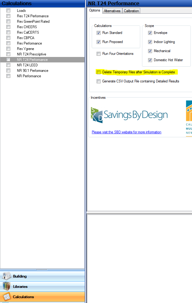
Interior surfaces are surfaces between two spaces and can be either walls, ceilings or floors. Note that interior walls can also contain doors. If you have an interior window, treat it as an interior door in an interior wall. Insert an interior surface in the room and set it adjacent to the other room. If you do not set it adjacent to another room, or you set it adjacent to itself, it is treated as adiabatic.
The top occupancy box titled ‘Occupancy’ is for general use. The lower box titled ’90.1 Ltg Occupancy’ is for lighting calculations based on ASHRAE 90.1. If you are not doing a an ASHRAE 90.1 calculation then you do not need to make any selection in the lower box.
Errors (139)
You are trying to run calculations that are related to the California Title 24 code. In order to run these calculations, you must select a location that is in the list of California locations. If you did not intend to run a Title 24 code calculation, then you need to select a different calculation. California locations have a Climate Zone selection between 1 and 16.
You can navigate to the top level of the Building Tree, and in the General tab, hit the Select button to select a location that is in California.
If you did not intend to run a Title 24 calculation, click on the Calculations button at the bottom left of the screen. In the list that appears above this selection, you will find all of the different calculations that can be run. Ensure that all Title 24 calculations do not have their boxes checked, and check the appropriate box for the type of calculation you intend to run.
You can now click the Calculate button on the menu bar to rerun your calculations.
You have selected the option to run a calculation that has not been activated on your computer. This usually means that you either have not purchased this particular calculation module, or you have not entered the necessary activation code to enable this calculation.
You can verify what calculations are activated on your computer by clicking on Help | Activated Modules. If you have the activation code that was sent by EnergySoft Sales, you can enter this under Help | Software Activation.
If you think this is a calculation that you have purchased, you can contact sales@energysoft.com for further help.
If this is not a calculation that you have purchased, click on the Calculations button on the bottom left. Above this button a list of calculations will appear. Find the calculation in this list and uncheck the box that tells EnergyPro to run the calculation.
You are trying to run a Single Family Calculation for this project, but it appears you have no valid Zones/Rooms entered that are designated as Single Family.
Begin by checking each Zone for a valid occupancy type. Below each Zone, verify that you have entered a square footage for each of the Rooms.
If you did not intend to run Single Family Calculations, you need to uncheck the option to run this calculation. Click on the Calculations button on the bottom left. Above this button a list of calculations will appear. Find the calculation in this list and uncheck the box that tells EnergyPro to run the calculation.
You have input a project with the Number of Dwelling Units input as greater than 2 and the building is designated as having more than 3 Stories. The Standards consider this building to be a Highrise Residential Occupancy.
You have checked the calculation option to perform a Lowrise Residential calculations, which would not be appropriate for this type of building.
You can change the Number of Dwelling Units at the Zone level of the tree, Dwelling Units tab. You can change the number of stories at the Zone level of the tree, General tab.
If you did not intend to run Lowrise Residential Calculations, you need to uncheck the option to run this calculation. Click on the Calculations button on the bottom left. Above this button a list of calculations will appear. Find the calculation in this list and uncheck the box that tells EnergyPro to run this calculation.
At the Zone level of the tree, you have input the Number of Floors as zero. You must enter a valid number that is one or greater.
At the Zone level of the tree, in the General tab, enter a valid number greater than zero.
When describing an HVAC system that uses a water heater to provide the hot ware for the space heat (Combined Hydronic), the software will perform calculations for the boiler that account for both the Domestic Hot Water usage as well as space heating usage.
Since the calculations must be done for both the HVAC and DHW usage, you must include BOTH calculations in your scope under the calculation options when modeling this type of system.
One option is to change the system type to a conventional system at the System Level of the Tree, Residential tab.
Your other option is to select the Calculations on the lower left. In the list that appears above, select the specific calculation you are running. On the right, check the options to include both Mechanical and DHW calculations.
At the top level of the Building Tree, you have selected a Location for the building, but the weather file associated with this location is missing from your computer. This weather file is required in order to perform the calculation you have specified.
At the top level of the Building Tree, click on the option for User Defined on the location. Now click on the Edit option and see what weather file location is specified.
You must now verify that this weather file location selected has a valid weather file located in the Program Files\EnergyPro 10\Weather folder on your hard drive.
In most cases, you should not specify your own location data. We suggest you uncheck the option for User Defined data and pick a stock location from the list of locations.
Your Domestic Hot Water heater has an invalid Energy Factor. Select the Libraries button on the bottom left. In the list that appears above, select the DHW/Boiler library. You will see your water heater listed in the library.
Verify that you have the correct type of water heater selected (Gas Fired, Electric, Heat Pump, etc).
Now verify that you have a valid Energy Factor input for the water heater. EnergyPro will list the valid range of Energy Factors that you must conform to.
Your Domestic Hot Water heater has an invalid Recovery Efficiency. Select the Libraries button on the bottom left. In the list that appears above, select the DHW/Boiler library. You will see your water heater listed in the library.
Verify that you have the correct type of water heater selected (Gas Fired, Electric, Heat Pump, etc).
Now verify that you have a valid Recovery Efficiency input for the water heater. EnergyPro will list the valid range of Recovery Efficiencies that you must conform to.
The Building you have described has Zones input as Multifamily Common Areas, but no Zones are input as actual Multifamily Dwelling Units. CBECC considers this as a Nonresidential Building, so all of the Zone Occupancies should be changed over to Nonresidential instead of Multifamily Common areas.
Make this change at the Zone level of the Building Tree, Zone Type input, or you could add into the model Zones designated as Multifamily Dwellings.
The Zone input in the Building Tree has the same name as another Zone in the Building Tree. The CEC compliance engine requires unique Zone names to run and document the project properly.
Note that EnergyPro will shorten your Zone names to conform to the CEC Compliance Manager length requirements, so only the first 25 characters of the name you have input is used. Make sure the first 25 characters of the name are unique.
The Zone Type selection is Nonresidential, but you have the Occupancy set to Residential Choice (Single Family, Multifamily, Hotel/Motel Guest Room). This is not a valid choice.
At the Zone level of the tree, General Tab, either mark the Zone Type as Residential or select a Nonresidential Occupancy from the list provided.
You are doing a Multi-Family project, and the total floor area entered under the Dwelling Units tab does not match the total floor area of the Zone. These two numbers must match.
At the Zone level of the tree, look at the Dwelling Units tab and make sure the total area (unit floor area times the number of units) matches the floor area for the zone. Do not use fractional values, as these usually do not add up.
In the Zone level of the tree, look at the entries for the Rooms under the Floor Area entry and be sure you have the correct numbers entered.
When modeling a project using the CBECC Com engine, the CEC requires that every zone have a valid floor to ensure a stable simulation within EnergyPlus. This means you either need a slab-on-grade if this zone has a ground floor slab, an exterior raised floor if this zone is over open space or crawlspace, or an interior surface designated with a floor assembly. The total of these surfaces needs to match the Conditioned Floor Area of the zone (which is the sum of the Room Floor Areas).
You have requested a Multifamily CUAC Calculation for this project. The Domestic Hot Water System is a central system. Utility costs cannot be determined for the individual dwelling units in this case.
At the Plant level of the tree, change the DHW system type to be individual Water Heaters for each dwelling unit.
You have requested a Multifamily CUAC Calculation for this project. The HVAC System is a central system. Utility costs cannot be determined for the individual dwelling units in this case.
At the System level of the tree, change the HVAC system type to be a non-central system for each dwelling unit.
The HVAC System is a single zone system and is serving a combination of Process Zones (Kitchen or Lab or Computer Room) and also Non-Process Zones (any other Occupancies). The CBECC Com engine does not allow you to mix these types of Zones on one single zone System. If you want to combine these on a Multiple Zone system (Packaged VAV, etc.) then you can.
In the Building Tree, you must change all the Zone Occupancy Types for this System to be either Process Zones, or Non-Process Zones.
The building has a one or more floors input in the tree with a floor assembly that includes a Crawlspace. The input for the exterior perimeter of the Crawlspace (length facing to the outside) is too small for a crawlspace of this size.
If you did not mean to enter a floor with a crawlspace, find the raised floor selections in the building tree and select a different floor assembly that does not have a crawlspace.
To change the Crawlspace Perimeter, go to the top level of the building tree, select the Misc tab and enter the correct value.
Highrise Residential occupancies are mandated to have ventilation systems by the code (balanced, exhaust or supply). These ventilation systems must be input at the Zone level of the Building Tree, Mechanical tab, in the Ventilation box. Note that the HVAC system itself cannot provide the ventilation, although it could be provided by a Dedicated Outside Air System that feeds to the HVAC. Each dwelling must be provided with ventilation according to the following formula:
CFM = Floor Area X 0.03 + (NBedrooms + 1) X 7.5 (NBedrooms cannot be less than 1)
You must ensure the ventilation input at the Zone meets this minimum criteria. Note that the floor areas and bedrooms are input at the Zone level of the Tree, Dwelling Units tab.
The Domestic Hot Water boiler you have input in the DHW/Boiler library has a Standby Loss value set to zero. The CEC requires a value for this type of water heater be entered that is greater than zero.
Check to make sure you intended to enter this type of water heater. Smaller, more common federally regulated water heaters do not require this input.
You can obtain this value from the manufacturer or from the CEC Appliance directory at www.energy.ca.gov. Click on the Libraries button on the bottom left. Select the DHW/Boiler Library in the list that appears above. Now find your water heater and enter the Standby Loss value.
You are trying to run a Nonresidential Calculation for this project, but it appears you have no valid Zones/Rooms entered that are designated as valid Nonresidential occupancy types.
Begin by checking each Zone for a valid occupancy type. Below each Zone, verify that you have entered a square footage for each of the Rooms.
If you did not intend to run Nonresidential Calculations, you need to uncheck the option to run this calculation. Click on the Calculations button on the bottom left. Above this button a list of calculations will appear. Find the calculation in this list and uncheck the box that tells EnergyPro to run the calculation.
A Domestic Hot Water heater has not been input. This selection is required for the calculations you are performing. At the Plant level of the tree, select the Domestic Hot Water tab. Select a DHW Boiler from the library of choices.
The Setpoint temperature for the heating side of the Hydronic loop is set to a temperature that is higher than the Cooling Tower minimum temperature. This Setpoint sets the lower limit of the condenser water loop on the Hydronic loop. Setting this temperature to a value that is higher than the high limit side set by the cooling tower will cause the boiler to try to heat the loop to this temperature while the tower is trying to cool the loop below this temperature.
A Setpoint temperature of 65 degrees is suggested for this input.
At the Plant level of the tree, In the Heating Hot Water Tab, lower the Boiler Setpoint temperature to a value that is below the cooling tower setpoint. As an alternative, go to the Hydronic tab and select the Cooling Tower and raise the Setpoint of the Cooling Tower above the boiler setting.
Zonal type systems such as Packaged DX, Split DX, Water Source Heat Pumps, Packaged Terminal Air Conditioners and Heat Pumps and Four Pipe fan Coil systems cannot be configured to serve more than one HVAC zone given the limitation of the thermostat controls. The CEC CBECC engine enforces this rule.
At the Zone level of the tree, make sure the system only has one Zone in the tree below the System, or choose a different system type designed to serve more than one Zone.
A valid name is required for all Zones in the Building Tree. The name must have at least one letter, and should be a unique name. At the Zone level of the building tree, enter a valid name.
The Zone you have input is a Residential Occupancy, but you have set the Zone Type to Unconditioned. Residential Occupancies are required to be conditioned.
At the Zone level of the Building Tree, either change the Zone Type to Conditioned, or change the Occupancy to a Nonresidential selection.
The airflow rate input for the HVAC system is not valid when modeling a conventional HVAC system. The CEC restricts the airflow rate on conventional systems to a mandatory minimum of 350 cfm/ton of airflow to a maximum of 550 cfm/ton.
At the System level of the building tree, in the ECC tab, edit the airflow setting and set this number to a valid rate.
Each wall/roof/floor/slab must have a valid construction assembly selected to perform the simulation. Leaving an assembly as “undefined” is not a valid choice. In this case, the surface has been designated as either New or Altered. In both cases, you must describe the new assembly. In the case of altered, this will describe the assembly after alterations are complete.
In the Building Tree, navigate to the surface and click on the New Assembly which is undefined and select a valid assembly from the construction assembly library.
The fenestration (window or skylight) has a glazing U-Factor that is not valid. You must input a valid U-Factor for the fenestration. The U-factor is the coefficient of conduction (heat transfer) for the fenestration product. This value is obtained from the manufacturer of the product.
In the Building Tree, navigate to the window or skylight and click on the fenestration selection. This will take you into the Fenestration Library where you can either select another product that is valid, or you can edit the fenestration U-Factor directly.
Each wall/roof/floor/slab must have a valid construction assembly selected to perform the simulation. Leaving an assembly as “undefined” is not a valid choice. In this case, the surface has been designated as either Existing or Altered. In both cases, you must describe the existing assembly. In the case of altered, this will describe the assembly before alterations are made.
In the Building Tree, navigate to the surface and click on the Existing Assembly which is undefined and select a valid assembly from the construction assembly library.
A valid selection for the Location (City) is required to perform calculations on your project. In the Building Tree, at the top level of the tree, General tab, click on the “Select” button and select a valid location from the list provided.
When modeling Packaged Multi-Zone Systems (System Type = Packaged MZ), the DOE-2 engine does not allow the use of a Water Cooled Condenser. This is a limitation of DOE-2, so you must either choose a different system type or remove the Water Cooled Condenser.
At the System level of the Building Tree, click on the Central System, this will take you into the Central System library. You can now select a different system, or edit the current system. You can change the System Type to another system, or navigate to the Cooling tab and change the Condenser Type to another choice.
The first zone listed below the HVAC system in the building tree represents the control zone when dealing with single zone systems. This zone will have a thermostat that will control the HVAC operation and cannot be input as an unconditioned zone.
In the building tree, at the System level of the tree, click and hold on a zone and you can then drag and drop that zone so that it is the first zone directly below the System icon.
Another option is you can edit the Zone and change the Zone Type to Conditioned.
The product is designated as having a Hydronic Heating system but no boiler has been specified. The boiler input is required when modeling Hydronic systems.
If you did not intend to model a Hydronic Heating system, navigate to the System level of the tree, and click on the Residential tab. Change the selection for the Hydronic Space Heating system to “None”.
If you did intend to model a Hydronic Heating system, navigate to the Plant level of the tree. If the system will be using a dedicated boiler, select a boiler from the library in the Heating Hot Water tab. If the system is a Combined Hydronic system (one that uses a common boiler for both space heating and domestic hot water), select a DHW boiler from the Domestic Hot Water tab.
When modeling Built-up VAV systems that include Fan Powered Zone Terminal Boxes, it is a requirement of the DOE-2 engine that you must have at least two zones.
If you did not intend to include Fan Powered Terminal Boxes, navigate to the Zone level of the tree, and select the Mechanical tab. You can now click on the Zone Terminal and select a different terminal box from the library, or you can edit your terminal box and change the type of box.
If you did intend to include Fan Powered Terminal Boxes, you just add an additional Conditioned Zone to this HVAC system (unconditioned zones don’t count).
Fan Powered Terminal Boxes (input at the Zone level of the building tree) can only be modeled with Chilled Water (Built-Up) Variable Air Volume (VAV) systems. This is a modeling limitation of the DOE-2 Simulation Engine. These types of terminal boxes cannot be selected when the system type is a Packaged VAV system.
At the Zone level of the Building Tree, in the Mechanical tab, you can select a different type of terminal box that is not fan powered, or you can edit the selected terminal box and change the type to a non-fan powered version.
At the System level of the Building Tree, you can select a different system type, or you can edit the current system type and change it to a Built-Up VAV system. However, keep in mind the Built-Up VAV system will require the definition of the chiller and pumps.
Some users have opted to model the fans as exhaust fans at the Room level of the building tree. Some have opted to model the DX compressor and an air cooled chiller and thus select the system type as Built-Up VAV.
You are trying to run a Nonresidential Calculation for this HVAC System, but it appears you have no valid Zones/Rooms entered that are designated as valid Nonresidential occupancy types.
Begin by checking each Zone for a valid occupancy type. Below each Zone, verify that you have entered a square footage for each of the Rooms.
If you did not intend to run Nonresidential Calculations, you need to uncheck the option to run this calculation. Click on the Calculations button on the bottom left. Above this button a list of calculations will appear. Find the calculation in this list and uncheck the box that tells EnergyPro to run the calculation.
Demand Control Ventilation (DCV) is a mandatory measure in the Title 24 Standards Section 120.1 in high density spaces. Zones that meet these criteria must be designated as having DCV controls to regulate the amount of outside air to the zone.
At the Zone level of the Building Tree, Mechanical tab, check the box for DCV, or at the General tab, select a different occupancy type that does not require the use of DCV.
Each HVAC system must have a valid central system selected to perform the simulation. Leaving a system as “undefined” is not a valid choice. In this case, the system has been designated as either Existing or Altered. In both cases, you must describe the existing system. In the case of altered, this will describe the system before alterations are made.
In the Building Tree, navigate to the System level of the tree and click on the Existing System which is undefined and select a valid system from the Central System library.
At the System level of the tree, in the Residential tab, you have indicated that you have a Whole House Fan (CFM and Watts have been input). This feature is only available on a home that has an Attic space, since the WHF is designed to cool both the house and the attic.
At the System level of the Tree, Residential tab, you should zero out the CFM input, or you should change your roof configuration so that the house has an Attic instead of Cathedral Ceilings.
Demand Control Ventilation (DCV) is a mandatory measure in the ASHRAE 90.1 Standards in high density spaces. Zones that meet these criteria must be designated as having DCV controls to regulate the amount of outside air to the zone.
At the Zone level of the Building Tree, Mechanical tab, check the box for DCV, or at the General tab, select a different occupancy type that does not require the use of DCV.
Interior surfaces can either be selected as floors, walls or ceiling/roofs. When inputting an interior floor it is input in the space that is above the other space. For instance on the second floor you would input and interior floor that is over the first floor. As part of this input, the elevation of the floor must be input. We recommend you leave the elevation at zero, the program will use the floor elevation input for the Room.
Many times, a floor is input into the first floor and is designated as being over the second floor. This is not possible. This type of input would be a ceiling/roof, not a floor. A floor must be input as being above another space, a ceiling as being below another space.
Review this input for this surface and be sure you intended to input a floor and not a ceiling/roof. The type of assembly selected determines this definition. Review the floor elevation and the room elevation to be sure they are consistent with the adjacent room.
Note that interior surfaces do not need to be input twice. Thus you would input either the ceiling of the first floor or the floor of the second floor but not both.
When modeling a slab on grade surface it is important to input the area of the slab as well as the exterior perimeter of the slab correctly. Make sure the exterior perimeter entered is less than the area of the slab.
The DOE-2 engine has a limitation that only allows you to model four central utility plants. The building tree contains more than four so this model cannot be run with DOE-2. You can generally simplify the model and combine plants, there is probably no circumstance where you need more than four independent hydronic chilled water/hot water loops in a building.
When inputting interior surfaces there is a selection at the bottom of the input screen to describe the room that this surface is “Adjacent To”. Without this input, the software does not know what this surface is next to. In the Building Tree, navigate to the interior surface and at the bottom of the input screen, click on the Adjacent To button. Select another room in the list that appears.
Note that inputting interior surfaces between rooms that are in the same zone is not necessary. The only impact you will see from this feature is if you have interior surfaces that are between different zones.
When doing compliance calculations, the software uses an engine developed by the CEC, the Compliance Manager. While the CEC’s published Joint Appendix 4 includes a very detailed list of assemblies as shown in EnergyPro, the CEC Compliance Manager does not implement the entire list.
The CEC recommendation is to open a copy of the Reference Appendices (Help | Title 24 | Reference Appendices), and find the U-factor for your proposed construction assembly in Joint Appendix 4 (also be sure to note the maximum U-factor from Section 150.0 of the standards). With that U-factor known, model a wood-framed assembly with a similar or slightly higher U-factor. Consider naming the construction to match what the builder will be constructing rather than what you modeled (e.g., call the R-30 wood-framed roof/ceiling with 0.032 U-factor that is substituting for your R-38, 0.031 U-factor, roof “R-38 metal framed roof” in case you use the file for a different job). Lastly, document for the plan checker what you did.
In the Building Tree, navigate to this surface, click on the Construction Assembly and either edit the current assembly by clicking on the green Import button or select another assembly from the library.
The Compliance Manager issued by the CEC has strict requirements on the number of surfaces that must be input into a Zone. Without a minimum of 3 surfaces for Nonresidential or 6 surfaces for Residential, the Compliance Manager will not produce stable results. Also, each Zone will need to have a floor and ceiling/roof to run properly.
Many times the project may not have that many surfaces. One approach you can take is to divide a wall into two pieces and meet the criteria. Also, interior surfaces next to another Zone count towards the six surfaces on both the Zone it is in as well as the Zone it is adjacent to.
When inputting the surface areas, do not try to trick the software by inputting one square foot surfaces. This will only result in the simulation failing to run. It is imperative that you input realistic surface sizes for the Zone being modeled.
The mandatory measures require that all heated slab floors must have slab edge insulation. A heated slab floor is a slab-on-grade assembly that has either electric or hydronic heating embedded in the slab. Refer to the Residential Compliance Manual for details on how this would be accomplished, along with insulation details.
In the Building Tree, navigate to the slab floor, and click on the Construction Assembly. You can now either select a different slab floor from the library, or edit the slab floor. To change this to a different selection, click on the green Import button and you will see two different lists of slab floors, Heated and Unheated.
If you select an Unheated Slab, the insulation is no longer required. If you select a Heated Slab, you must choose one from the list with a minimum insulation level that meets the requirements in the mandatory measures section of the code for your climate zone.
When describing surfaces for a Zone, there will generally be four walls, and floor and a ceiling/roof. Looking at the geometry of these inputs, it would not be possible that any individual surface in that zone could be larger than all of the remaining surfaces. This indicates either an input error for the square footages, or there are surfaces that have not been included when describing the Zone, and the CEC Compliance Manager will not run.
Note that interior surfaces are included in this tabulation, so be sure interior surfaces in other zones have the “Adjacent To” set properly so this Zone includes that surface in the tabulation.
Check your inputs for this Zone and verify the correct square footages for each surface and make sure you have both floors and ceiling/roofs input.
When modeling HRV or ERV systems, the software requires two ratings, taken from HVI (Heating and Ventilating Institute) Directory. The ASRE (Adjusted Sensible Heat Recovery) and the SRE (Sensible Heat Recovery) Ratings. The ASRE must be at least equal to the SRE rating.
At the Zone level of the Building Tree, in the Dwelling Units tab, check your inputs for these two ratings under the IAQ fan heading.
When inputting custom curve data points for a Heat Pump HVAC System, as the outdoor drybulb temperature decreases, the output of the heat pump should also decrease since the heat pump will have less capacity at lower temperatures.
Edit the data for the Central System on the Curves tab such that at lower temperatures, the system will have less output than at the higher temperatures.
At the Zone level of the building tree, this Zone is specified as a Restroom or Shower rooms, under the Ventilation Function. Per table 140.1-B in the Code, you are required to specify the quantity, for the purpose of Mandatory exhaust requirements.
You can opt to change the Ventilation Function at the General Tab, or input the Quantity at the Mechanical Tab, along with the General Exhaust fan CFM being provided to meet this requirement.
Your HVAC system serves zones with a mix of occupancy types. You cannot mix a Nonresidential or Hotel/Motel occupancy on the same system that serves either a Multifamily dwelling unit or a Multifamily common area.
In the Building Tree, at the Zone, change all zones on this system to either be Multifamily/Multifamily Common or Nonresidential/Hotel/Motel Zone Types.
The Water Heating System {0} has the either the Tank and/or Condenser marked as located Inside. The Inside Zone is not a Multifamily occupancy. This cannot be marked as being in a Nonresidential Zone.
At the Plant level of the Tree, DHW tab, either uncheck the Tank/Condenser as being Inside, or select a different Zone location for the given component. It can be either a Multifamily Occupancy or a Multifamily Common area.
CBECC performs a Cooling Tower simulation that will become unstable if the tower water DeltaT is not within specified limits. The tower size you have specified, combined with the condenser water flow rate is outside these limits needed for the simulation. You can either adjust the tower size (tonnage), or adjust the flow rate (gpm) to bring the resulting DeltaT with the acceptable limits of 5-20 F.
Modeling of heat pumps requires data be included for the system heating output at both the 47 and 17 degree AHRI outdoor design rating conditions. Manufacturers publish both sets of data in their literature, and this same data is also listed in the AHRI listing and sometimes in the CEC equipment directories.
In the Central System Library, in the Heating Tab, enter the Heating Output for the heat pump based upon both rating conditions.
When a heat pump is input, the software requires that the heating capacity of the unit be given at two rating conditions. The first rating condition is when the outside ambient drybulb is at 47 degrees F. The second rating condition is when outside conditions are at 17 degrees F. At both conditions, the manufacturer’s rated output needs to be input into the Central System Library entry for the heat pump.
At the Central System library, in the Heating tab, enter a value for the Heat Pump heating output at the 17 degree condition.
Variable Refrigerant Flow (VRF) system modeling includes describing both the outdoor condenser unit of the system as well as the indoor evaporator units at each of the zones. Each manufacturer places restrictions on how much indoor unit capacity can be coupled to a particular outdoor unit. EnergyPro will check how much indoor unit capacity has been specified and ensure that this falls within the acceptable limits of the VRF manufacturer.
You should review the VRF modeling guide at www.energysoft.com under the Support section of the website.
Verify the total capacity of each outdoor condenser unit that has been input at the System level of the building tree. Navigate to each Zone under that particular system, and verify the capacities of the indoor units that have been input at the Mechanical tab for the Zone. This total installed capacity of indoor units must fall within the parameters of the manufacturer.
When inputting the efficiency of the HVAC system, ensure the value entered is consistent with the type of system being modeled. If it is small furnace, the value would be an AFUE that is in the range of 0.7 to 1.0, while a small heat pump would have an HSPF in the range of 7 to 12. Double check that you have entered this value correctly by selecting the HVAC system in the System level of the Building Tree and reviewing the inputs in the heating and cooling tabs.
Cooling systems are described with two efficiency metrics, the Energy Efficiency Ratio (EER) and the Seasonal Energy Efficiency Ratio (SEER). The SEER represents the seasonal average performance across the cooling season and will be higher than the EER, which represents the performance at 95 degrees.
At the System level of the tree, select the HVAC system. In the Cooling tab, review your inputs for the SEER and the EER and ensure the EER falls within the range specified in the error message, as the value is likely not valid, or alternatively revise the SEER.
Each Zone entered into the Building Tree is required to have an Elevation entered for the Zone that describes the distance above the exterior grade of the building. Thus, a ground floor Zone with a slab on grade would have an elevation that is 0.7 feet above the exterior grade. Each floor of the building will require this value be input.
In addition, each Zone is required to have the Floor to Floor height entered that describes the distance from the Zone floor elevation to the Zone above floor elevation. If the Zone that is above another Zone does not have a floor elevation that is at least equal to the lower floor elevation plus the floor to floor height, this is an error.
At the Zone level of the Building Tree, navigate to the Building Story input. Each unique level of the building (story) should have an entry. Example, Floor 1, Floor2, etc.
Review the inputs for Floor Elevation and Floor to Floor Height for each Zone in the Building Story, and ensure these values have been input consistently.
Note that it is valid to have a single Zone that encompasses more that one floor of the building, you would simply select the lower story for that Zone.
At the Zone level of the Building Tree, a Zone Terminal box has been input as well as the Heating and Cooling Airflow values. The heating flowrate for this zone is lower than what is needed to provide the minimum code required ventilation for the zone.
At the Zone level of the Building Tree, in the Mechanical tab, compare the Heating Airflow input to the code required airflow reported in this message. Note that while you may have chosen to input lower ventilation rates in the Room Occupancy tab, the code minimum specified by the CEC in the CBECC ACM manual tables will always be used as the minimum so you cannot go below this number.
When modeling Zones, each surface in the Zone must have a unique name. This is a rule enforced by the CEC Compliance Manager. Note that when inputting names, only the first 25 characters that you input are considered, so ensure the names are reasonably short, and unique.
At the Building Level of the Tree, navigate to the surface and edit the name so that is it unique.
Under the Distribution tab at the System level of the tree, you are given the option of selecting the location of the ductwork. When the location has been set to Attic, the CEC Compliance Manager requires that the total size of the attic must be at least 10% of the total square footage of the home. Without an attic of at least this size, there is insufficient space for the model to include the total volume of ductwork.
You have the option of changing the location of the ductwork by editing this input and selecting another location if your attic area does not meet this criteria.
If you think you have attic area that is 10% or more, navigate to each roof in the building tree. Review the area input for each roof. Also, click on the construction assembly and verify that you have selected a roof construction that includes an attic, and not a cathedral roof type construction.
The Light Fixture you have selected has included an input below the fixture for a Control for Credit Lighting Power Density adjustment per Table 140.6-A in the Title 24 Standards. The control referenced is not valid for the type of occupancy selected for this Zone.
Please review the valid applications of this control in Standards Table 140.6-A and make sure you have selected a valid control. You can either change the control or change the occupancy at the Zone level of the tree.
Under the Distribution tab at the System level of the tree, you are given the option of selecting the location of the ductwork. When the location has been set to Garage, the CEC Compliance Manager requires that you must have a Zone in the building tree input that has the Zone Type set to “Res Garage”.
You have the option of changing the location of the ductwork by editing this input and selecting another location if you don’t have a garage.
If you think you have input a garage, navigate to each Zone in the building tree. Review the Zone Type input for each Zone, one should be “Res Garage”.
Under the Distribution tab at the System level of the tree, you are given the option of selecting the location of the ductwork. When the location has been set to Crawlspace, the CEC Compliance Manager requires that the total size of the crawlspace must be at least 15% of the total square footage of the home. Without a crawlspace of at least this size, there is insufficient space for the model to include the total volume of ductwork.
You have the option of changing the location of the ductwork by editing this input and selecting another location if your attic area does not meet this criteria.
If you think you have crawlspace area that is 15% or more, navigate to each exterior floor in the building tree. Review the area input for each floor. Also, click on the construction assembly and verify that you have selected a floor construction that includes a crawlspace.
The Light Fixture you have selected has included an input below the fixture for an Additional Allowance as described in Table 140.6-C in the Title 24 Standards. The Additional Lighting Allowance referenced cannot be used on the type of occupancy selected for this Zone.
Please review the Additional Lighting Allowances in Standards Table 140.6-C and make sure you have selected a valid selection per this table. You can either change the Additional Allowance selection for the light fixture or change the occupancy at the Zone level of the tree.
The Lighting Elements in the building tree have an entry for the Fixture Reference Code, as well as the Luminaire listed in the library. When entering a Reference Code, it has to match the Luminaire in the library throughout the tree.
In other words, using Reference Code F-1 for fixture A, and then using Reference Code F-1 for fixture B would not be valid {0}. Fixture B would require a different reference code, this is required to build the fixture list as part of the documentation on the forms.
Check your Luminaire Selection and Reference Code to ensure they are correct at each entry in the Building Tree.
The HVAC System has been input with an Evaporatively Cooled Condenser, but the EER rating at 95 degrees for the unit has been input as being higher than the EER rating at 84 degrees. Since the EER84 rating is at 84 degrees and the EER95 rating is at 95 degrees, the EER84 rating should always be higher than the EER95 rating.
Either change the EER84 or EER95 rating so that the EER84 is higher than the EER95 rating.
In the location listings, you have the option of selecting a location, and also you have the option of editing the location using the User Defined option. You have edited the location and you have not selected a valid DOE Climate Zone. In the Location Selection you must edit your Location and select a valid DOE Climate Zone. We suggest not using the User Defined feature, but rather that you select a stock location from the listings.
Your HVAC System is marked as either New or Altered, but you do not have a New Mechanical System selected at the system level of the tree. An HVAC system is REQUIRED for the type of calculations you are performing.
In the System menu of the Building Tree, select a System from the Central Library.
Your Heat Pump system requires a valid Cooling Output. Check the Manufacturer’s specification and enter the correct Cooling Output at the Central System library entry in the Cooling Tab
The current CEC CBECC engine will not allow you to set the fan CFM at zero (such as when modeling a radiant system). You must enter a CFM for the Supply Fan on all HVAC Systems.
All fans that are input into EnergyPro require a valid motor power rating (either input as the Brake Horsepower (BHP), the Nameplate Horsepower, or the Input Wattage). This applies to any fans in which you have input a flow rate (CFM) in order for the CBECC Com engine to simulate the fan.
In the Central System Library, check the Fan tab for valid inputs for the Supply Fan and optionally the Return Fan.
In the Zonal System Library, check the Fan tab for any fan powered terminal boxes and equipment.
At the Zone level of the tree, check the Mechanical tab for valid inputs for the Exhaust Fan.
When defining an HVAC system, it is a requirement of the CBECC Com calculation engine that ALL HVAC system must have a capacity entered for the system. The software will not auto-size capacities, it is your responsibility to define this number.
At the Central System Library, edit the HVAC system and add a Heating and/or Cooling output for the HVAC system identified in this message.
Title 24 Standards section 110.6 mandates that any Nonresidential buildings with Site Built Vertical fenestration cannot use the Center of Glass inputs in the fenestration description.
In the Fenestration Library, edit your inputs for the fenestration rating type and either change it to either NFRC rated or Default values. Note that using Defaults will rarely comply.
You have left the Floor Area for the room set to zero. A Floor Area entry is required for all Rooms in the building tree. If you double click on the Error this will take you to the Room in the Building Tree where you should enter a valid value greater than zero.
When defining openings in a wall that include shading features (Overhangs or Sidefins) you must define the geometry of the Wall (Width and Height) as well as the geometry of the Windows and Doors (Width, Height) as well as the location of the opening on the Wall (XPos, YPos). The XPos and YPos are the position of the bottom left corner of the Window or Door on the Wall.
If the Window/Door Height + the YPos exceeds the total wall height, the surface is located out of the boundary of the Wall.
If the Window/Door Width + the XPos exceeds the total wall width, the surface is located out of the boundary of the Wall.
Check your inputs for the wall dimensions, as well as your inputs for the Window/Door dimensions as well as the relative X/Y positions for validity.
At the Zone level of the Building Tree, an input is provided for the Story of the building the Zone is assigned to. In that list, each Story is required to have a unique name that describes the particular Story. As an example, Floor 2 could be used to describe the second story of the building.
Each name in this list must be unique, duplicate names are not permitted. Check this list and ensure each Story is assigned a unique name.
The Floor to Floor Height for the Zone can never be less than the Ceiling Height. This Ceiling Height must always be less than the floor to floor height.
At the Zone level of the tree, in the Building Story input, either increase the Floor to Floor Height, or decrease the Ceiling Height.
You are analyzing an Addition alone, and the Existing Floor Area is set to 0. In the case of an Addition, the Existing Floor Area of the building must be entered.
Navigate to the top level of the Building Tree and enter the Existing Building Floor Area.
If you are not modeling an Addition alone, navigate to the top level of the tree, and change the Building Type.
At the System level of the Building Tree, you have an HVAC system input with the “Outside Air From” setting configured to receive outside air from another HVAC system. That other HVAC system has not been defined and must be properly configured for the simulation to run.
Select a valid HVAC system for your DOAS system from the Central System library.
At the Zone level of the Building Tree, a Zone Terminal box has been input as well as the Heating and Cooling Airflow values. The cooling flowrate for this zone is lower than what is needed to provide the minimum code required ventilation for the zone.
At the Zone level of the Building Tree, in the Mechanical tab, compare the Cooling Airflow input to the code required airflow reported in this message. Note that while you may have chosen to input lower ventilation rates in the Room Occupancy tab, the code minimum specified by the CEC in the CBECC ACM manual tables will always be used as the minimum so you cannot go below this number.
At the Zone level of the Building Tree, a Zone Terminal box has been input as well as the Heating and Cooling Airflow values, and the Minimum CFM Ratio for the Zone Terminal Box. The Minimum turndown for this zone is lower than what is needed to provide the minimum code required ventilation for the zone. The minimum turndown airflow rate is equal to the Cooling Airflow times the Minimum CFM Ratio input for the Zone Terminal Box.
At the Zone level of the Building Tree, in the Mechanical tab, compare the Cooling Airflow input and the Minimum CFM Ratio to the code required airflow reported in this message. Note that while you may have chosen to input lower ventilation rates in the Room Occupancy tab, the code minimum specified by the CEC in the CBECC ACM manual tables will always be used as the minimum so you cannot go below this number.
Note that if you have checked the box for Demand Control Ventilation (DCV) your terminal box is allowed to turndown the airflow to 0.15 cfm/sqft and thus the minimum ventilation rate will be reduced in this case.
When modeling an Underground Surface, the Depth below Grade is a required input and cannot be set to Zero.
At the Underground Surface, edit this value to match the depth below grade for the Basement Zone.
The surface you have input has an area of zero which is not a valid surface and the simulation will not run. You either need to edit the surface in the Building Tree and input a valid surface area, or you need to delete the surface from the Building Tree.
At the system level of the tree, you have input one or more HVAC systems with an identical name. The CEC CBECC engine uses the system name in the simulation and reports and requires that all systems in the building have a unique name.
Navigate to the System level of the Building Tree and edit the name shown. Note that you do not need to edit the name in the Central System library, that name does not have to be unique. Only the name shown in the Building Tree at the system level will need to be edited.
You have input either a window or a skylight into the Building Tree. In that entry, you have selected a Fenestration product from the Fenestration Library. The fenestration selected is the wrong type.
Click on the Fenestration item in the building tree, this will take you into the Fenestration Library. Review the entry for Fenestration Type, if this is a skylight, it needs to be set accordingly. If it is a Vertical Fenestration product, ensure the appropriate selection is made.
Note that if you have both windows and skylights using the same fenestration entry, you will need to create two entries in the library, one for windows, another for skylights.
You are modeling a Highrise Residential project and have failed to input the correct number of stories for this occupancy type. Highrise residential projects are considered four stories or more.
At the Zone level of the tree, review each entry for the Floor Number input. You must ensure that this is set to four or more. If your project is in fact less than four floors, you need to change the Zone Occupancy input to Multi-Family and run the Res T24 Performance calculation instead.
At each Zone is an input for the Number of Floors which determines how many stories for this particular zone. So if a zone being modeled included both the second and third floors of a building, it would be set to two since that zone included two floors. Normally you would set this to one and model each floor as a zone. The CEC CBECC engine will not allow this number to be greater than 3, which means the zone you are modeling consists of all three floors of a building. While you might have a zone that exceeds 3 floors this particular input cannot be greater than 3.
To correct this, go to the Zone and change this number to no more than 3.
At the Zone level of the Building Tree there is an input for the Accessory Dwelling Unit (ADU) that includes the choices of No, Attached or Detached. You have designated more than one Zone as being an ADU and this is not permitted by the modeling tools.
You must either change the setting in the Zone to no, or you must combine the various Zones designated as being ADU into a single Zone.
The area of this surface is greater than 40% of the total surface area of this zone, which includes both child surfaces and Interior walls and floors which are next to this zone.
This is not physically possible to have a single surface this large relative to all other surfaces in a zone, since that zone as a minimum will have walls, ceilings and floors that will prevent this circumstance.
You have either made a mistake in the area of this surface or you have forgotten to input all of the other surfaces in the Zone.
Either reduce the size of this surface, or increase the areas of other surfaces in the Zone.
The total area of Interior walls which are adjacent to your Zone is greater than 40% of the total surface area of this zone, which includes both child surfaces and Interior walls and floors which are next to this zone.
This is not physically possible to have a single surface that large relative to all other surfaces in a zone, since that zone as a minimum will have walls, ceilings and floors that will prevent this circumstance.
You have either made a mistake in the area of this surface or you have forgotten to input all of the other surfaces in the Zone.
Either reduce the size of this surface, or increase the areas of other surfaces in the Zone.
The total area of Interior floors which are adjacent to your Zone is greater than 40% of the total surface area of this zone, which includes both child surfaces and Interior walls and floors which are next to this zone.
This is not physically possible to have a single surface that is that large relative to all other surfaces in a zone, since that zone as a minimum will have walls, ceilings and floors that will prevent this circumstance.
You have either made a mistake in the area of this surface or you have forgotten to input all of the other surfaces in the Zone.
Either reduce the size of this surface, or increase the areas of other surfaces in the Zone.
When modeling Multifamily occupancies, any interior surfaces you have input need to have the room on the other side identified, this is the Adjacent To entry. This ensures a stable CBECC simulation. In the message shown in EnergyPro, double click and EnergyPro will take you to the Interior Surface in question. There you can enter the Adjacent To that identifies the room on the other side of the surface.
You have selected an HVAC system that is a multiple zone Variable Air Volume (VAV) system. This type of system requires that you input the Zone Terminal Boxes for each zone served by the system. If a zone does not have any terminal boxes, simply input a terminal box that is Constant Volume for the modeling.
To input the terminal box, go to the Zone level of the Building Tree, in the Mechanical tab you will select an appropriate Zonal System for the zone.
The HVAC System you have selected is not a system type currently supported by the CEC CBECC engine. The CEC does not currently have this type of system implemented in the Compliance Manager but will be implementing it in an upcoming version.
For now, please select a different system type or just input a smaller system.
You are modeling a VRF system in Version 6 or 7 (this FAQ does not apply to version 8), and since the VRF modeling is not approved by the CEC for Title 24 permit application, you cannot use the VRF system type in EnergyPro. For Title 24 permit submittals, you must model the units as a series of minimum efficiency split system heat pumps. Model all of the ‘indoor units’ as their own outdoor unit (in the Central System Library, and at the System level of the Tree) and the outdoor unit does not get modeled. The heating and cooling capacity, fan airflow and design power should all come from the indoor unit specs. Don’t model an outside air economizer in the outside tab. You can use the System Multiplier in the Building Tree if any of the units are identical. The heating and cooling efficiencies would be the standard code minimum efficiencies.
3 Phase – 13 SEER, 11 EER, 7.7 HSPF
1 Phase – 14 SEER, 11.7 or 12.2 EER, 8.2 HSPF
Please also reference the Appliance Efficiency Standards for the standard efficiencies.
You have input an Interior Surface that has a very large surface area. In this case, the interior surface are is larger than the sum of all other surfaces in the Zone it is adjacent to. This is not physically possible to have a single surface that is larger than all other surfaces in a zone, since that zone as a minimum will have ceilings and floors that will prevent this circumstance.
You have either made a mistake in the area of this surface or you have forgotten to input all of the other surfaces in the Zone.
Either reduce the size of this surface, or increase the areas of other surfaces in the adjacent Zone.
You have selected an HVAC System that is a Hydronic Heating System, which can only be modeled by the CEC CBECC engine if the heating boiler is Gas Fired (not a Heat Pump or Electric Resistance boiler). In this case you are using are not using a Gas Fired unit for the boiler and this cannot be modeled.
Either change your system type to a Non-Hydronic system at the System level of the Tree, General tab, or at the Plant level of the tree, Heating Hot Water Tab, select a Boiler that is Gas Fired.
The approach to model an Electric boiler or Heat Pump Water Heater that provides space heating is to treat it as an electric space heater, and indicate no ducts. This is a CEC rule, not a program limitation, so you should consider an alternative system.
The project has been identified at the Top level of the Building Tree as a Addition Alone. When analyzing this type of project, the HVAC system must either be defined as Existing or New. You cannot select Altered.
If you wish to analyze the HVAC system as being Altered, you must input the entire Existing portion of the building into the building tree. At the top level of the Building Tree, change the Building Type to Existing + Addition/Alteration.
Your other option is to go to the System level of the Building Tree and change the System Type to New or Existing.
At the System level of the Building Tree, you have specified HVAC systems that include chilled water coils. You have not input a chiller to serve these coils at the Plant level of the Building Tree.
Go to the Plant level of the Building Tree, and in the Chilled Water Tab, input the chiller and associated chilled water pumps for the HVAC system.
You have defined equipment in this building that requires a boiler. This could include hot water coils at the air handler, zone terminal box heating coils, or in the case of a water source heat pump, a condenser water loop that requires a boiler. You are required to input a boiler and hot water pumps.
Go to the Plant level of the Building Tree, and in the Heating Hot Water Tab, input the boiler and associated hot water pumps for the HVAC system.
When equipment is defined at the central plant such as Boilers, Chillers, Cooling Towers and or DHW Systems (including Hydronic Heat Pumps) you must be sure to define the pump associated with that piece of equipment.
To correct this problem, go to the Plant Level of the Building Tree, and go into either the Heating Hot Water, Chilled Water, Hydronic or Domestic Hot Water tab and define the flow rate and pump power for pumps identified in this error message.
When inputting Interior Surfaces, you have the ability to indicate the Zone that the surface is Adjacent To as part of the inputs. Since different Zones can have different Floor Multipliers, the CBECC engine requires that the Zones on each side of the interior surface must have the same Floor Multiplier.
If you wish to change the Floor Multiplier, go to the Zone level of the Building Tree and click on the Building Story. From there you can edit the Floor Multiplier.
Another option is to edit the Interior Surface and change the Adjacent To setting to be another Zone that has the same Floor Multiplier, or you could even set the surface as Adjacent To itself.
You have defined equipment in this building that requires a cooling tower. This could include water cooled chillers or in the case of a water source heat pump, a condenser water loop that requires a cooling tower. You are required to input a cooling tower and condenser water pumps.
Go to the Plant level of the Building Tree, and in the Chilled Water tab (for chillers) or in the Hydronic tab (for water source heat pumps), input the cooling tower and associated condenser water pumps for the HVAC system.
When inputting Underground Walls, the CBECC Res engine will only allow a wall construction assembly which is either Concrete, Insulated Concrete Form (ICF) or Brick. For Underground Walls, you must select a construction assembly from the library which is one of these types, you cannot use conventional frame walls, and CMU walls are also not supported currently.
In the Building Tree, you must either select a different construction assembly that fits this description, or edit the construction assembly you have selected, hit the green Import button and import either a Concrete, ICF or Brick wall from the JA4 selections.
It is acceptable to add framing and insulation to the concrete wall once selected, however, in the Res T24 Perf tab.
You are trying to perform a Prescriptive Calculation on a project specified as New Construction (New Home). The Prescriptive calculation is only valid for Additions and Alterations and can produce the CF1R-ADD and the CF1R-ALT. For a new home, the CF1R-NCB must be produced and registered with an ECC provider, we have no way to upload that information to the ECC provider.
This project should be run under the Performance approach instead.
In the Assembly Library, you have forgotten to define the Layers for your construction assembly. At least one layer must be defined.
Go to the Assembly Library on the bottom left of the screen under Libraries, select this assembly and navigate to the Layers tab on the right. Double click on a blank layer and select an appropriate material from the list.
Your system type has been input as a Variable Air Volume system, which allows the airflow to be modulated down to a minimum airflow during low load conditions, However, code does not allow that airflow to drop below the minimum ventilation rate for the zones served.
To fix this, go into the Central System Library, and select your HVAC system. At the Fans tab, increase the Minimum Airflow to be at or above the code requirement for Ventilation.
When modeling conditioned spaces under Title 24, all spaces are required to be ventilated per the code. At the Zone level of the tree, in the Mechanical tab, you have set the Ventilation to None. This is not a valid choice, so either choose that it comes from the HVAC system, from an Exhaust Fan, or it is Naturally Ventilated. Note that the Natural Ventilation choice is only valid for Residential spaces and cannot be used for Commercial spaces.
When modeling conditioned spaces under Title 24, all spaces are required to be ventilated per the code. At the Zone level of the tree, in the Mechanical tab, you have set the source of ventilation as being provided by the HVAC system. The HVAC system is specified as having the fans cycle with the load, which will not provide continuous ventilation, or it has no ducts.
You have a number of choices here:
At the Zone level of the Building Tree, in the Mechanical tab, choose another source of ventilation, such as a local exhaust ventilation fan. Note that the Natural Ventilation choice is only valid for Hotel/Motel Guest Rooms and cannot be used for other spaces.
If this is a VRF system, change the Indoor Unit fan specification and remove the option for Fan Cycles with Load.
For other systems, change the Central System option in the Controls tab to have the fan run continuously.
Add a Dedicated Outside Air System (DOAS) to provide the ventilation.
When modeling conditioned spaces under Title 24, all spaces are required to be ventilated per the code. At the Zone level of the tree, in the Mechanical tab, you have set the Ventilation to Natural Ventilation. The Natural Ventilation choice is only valid in the software for Hotel/Motel Guestrooms (2016 Title 24 also allows it in Highrise Res) and cannot be used for other occupancies. This setting needs to be change to either a Ducted HVAC System, or to an Exhaust Fan.
In the Title 24 Standards section 120.1, the code mandates a minimum exhaust rate based upon the occupancy of the space. When you select the Zone Occupancy and Ventilation function in the General tab, this information is determined.
One choice is to select a different Ventilation function for the Zone. Go to the Zone and click on the General tab and click the Select button to change the Ventilation function.
The other choice is to go to the Zone and click on the Mechanical tab and specify an exhaust fan that will provide the exhaust rate shown on that tab.
Title 24 Standards section 140.9 regulates Kitchen Hoods, and contains a table that specifies the maximum exhaust flow for a hood. Hoods that are Eyebrow style may not be used in Heavy Duty or Extra Heavy Duty applications. Hoods that are Backshelf / Passover style may not be used in Extra Heavy Duty applications.
To correct this, go to the Zone level of the Tree, Mechanical tab and select a lower duty rating for the hood.
Central Hot Water systems used in Multifamily applications cannot have the Distribution entry set, other than to choose either Standard or (ECC Req’d) Pipe Insulation, All Lines. The other choices are not valid in this application. You can either uncheck the box indicating this is a Central system or change your selection under Distribution.
At the Zone level of the Building Tree you have set the Occupancy Type to a Nonresidential Occupancy selection. Since you are doing a Single Family calculation (Single Family Title 24 Performance), all occupancies must be Single Family. Any other selections in that list fall under Nonresidential occupancies.
Go to the Zone level of the Building Tree and designate the Zone Occupancy selection as Single Family.
At the Zone level of the Building Tree you have set the Occupancy Type to either a Single Family or Multi-Family selection. Since you are doing a Nonresidential calculation (Nonresidential Title 24 Performance), no occupancy can be set to Single Family or Multifamily.
Note that a Zone Type of Res Garage is also considered a Single Family occupancy.
Go to the Zone level of the Building Tree and designate the Zone Occupancy selection as any selection in the list other than Single Family or Multi-Family and ensure the Zone Type is not set to Res Garage.
When defining a Variable Refrigerant Flow (VRF) system, two components must be defined in the Building Tree. The Outdoor Condenser is defined at the System level of the tree, and each Indoor Evaporator unit is defined at the Zone level of the tree. Each Zone is required to have an Indoor unit defined.
To define the indoor unit, go to the Zone level of the Building Tree, and in the Mechanical tab, click on the Zonal unit. Select an Indoor unit that has the type specified as Variable Refrigerant Flow.
When entering a light fixture in the Building Tree, it is a requirement that you input the Reference Code for that fixture. Typically, this will be indicated on the lighting fixture schedule on the plans.
The DOE-2 simulation used for the ASHRAE 90.1 and Nonresidential Performance calculations is not able to simulate an exhaust fan with variable flow at the zone. The solution is to model this as part of the return fan for the HVAC system, and this may also mean that the system is marked as being 100% outside air.
This edit would be made by removing the exhaust fan from the Zone level of the Tree, and inputting it as part of the HVAC system, which is one level up in the building tree.
The VRF Indoor Unit you have entered in the Zonal Library does not have a Heating and/or Cooling capacity entered. The current simulation requires both and Heating and Cooling Capacity for VRF Indoor Units.
Navigate to the Zone level of the Building Tree, in the Mechanical Tab, click on and edit the Indoor Unit and enter the capacities.
At the Zone level of the tree, Mechanical tab you have specified that the ventilation will come from the HVAC system under the input for Ventilation Type. The code does not permit the use of the HVAC system as a source of ventilation, you must provide a dedicated ventilation system to ventilate a Hirise Residential Occupancy.
This could be an exhaust fan input at the Zone Mechanical Tab under Ventilation, a Supply Fan, or a DOAS system.
At the Zone level of the Building Tree, in the Mechanical tab, choose Zone Ventilation Fan as the source of ventilation and input the Airflow and motor watts for the Exhaust Fan under Ventilation, or include a DOAS system to provide the ventilation.
You have chosen to use an Exhaust Fan to provided the mandated Outside Air Ventilation for your zone. You are required to define the Airflow for the exhaust fan, as well as the motor fan power.
At the Zone level of the Building Tree, Mechanical tab, input a valid exhaust fan that will be large enough to meet the ventilation required for this zone.
The HVAC System is input as a ducted Gas Fired system with Cooling. This type of system has a maximum fan power limitation of 0.45 w/cfm in cooling mode.
You can either change your system type to something other than a ducted Gas Furnace, or you must go to the System level of the Building Tree and in the ECC tab set this value to 0.45 w/cfm or less.
When modeling a space designated as a Parking Garage area, you are required to set the Occupancy to Unconditioned. Go to the Zone level of the Building Tree, and in the General tab, set the Occupancy to Unconditioned.
When defining Lighting elements in the Building Tree, you must select either an Existing or New Luminaire (or both for Alterations) from the Luminaire Library.
When modeling Closed Circuit Cooling Towers, the setpoint on the tower must be at least 10 degrees higher than the outdoor summer drybulb temperature to ensure a stable simulation. This is a requirement of the CBECC engine.
To solve this problem, edit your Cooling Tower, and change the Setpoint Temperature input to a value that is at least 10 degrees above the Summer OADB.
When modeling Closed Circuit Cooling Towers, the simulation requires a maximum Delta T of 15 degrees F across the air side of the tower. To accomplish this the fan CFM must be kept to a minimum level to prevent the Delta T going above 15 degrees.
Edit the Cooling Tower, and on the Fan tab, increase the CFM of the fan.
When modeling multiple zones on a single zone system, EnergyPro will “combine” the zones for the purposes of reducing the unmet load hours. Basically, the program puts all the zones onto a single thermostat. However, the CBECC simulation does not allow these zones to reference different Stories.
At the Zone level of the Building Tree, change the Building Story entry to be the same. You can input an average ceiling height if necessary.
When modeling multiple zones on a single zone system, EnergyPro will “combine” the zones for the purposes of reducing the unmet load hours. Basically, the program puts all the zones onto a single thermostat. However, the CBECC simulation does not allow these zones to have multiple exhaust fans, and they must all be on the first zone.
At the Zone level of the Building Tree, you can put all of the exhaust fans into a combined exhaust fan on the first Zone listed under the HVAC System.
You have indicated that you have an Energy Recovery system, as the Zone level of the Tree, Mechanical or Dwelling Units tab. However, the Adjusted Sensible Heat Recovery (ASRE) rating, taken from the Heating and Ventilating Institute (HVI) listing shows that this number is LESS than the Sensible Recovery Efficiency (SRE) from the same listing. This number must be greater than the SRE rating.
At the Zone level of the Building Tree, Mechanical or Dwelling Units tab, please review your inputs for the ASRE and SRE ratings.
Your HVAC system incorporate a Dedicated Outside Air System (DOAS) to provide the Outside Air ventilation for the Zone identified in this message. At the mechanical tab, you have not specified a valid Cooling Supply Air flowrate from the DOAS to provide the ventilation air. This CFM must fall between the minimum required OA but cannot exceed the airflow specification given for the VRF terminal unit (Zonal System).
At the Zone level of the tree, Mechanical Tab, change the Cooling Supply Airflow rate per the messaging requirements.
When a Dedicated Outside Air System (DOAS) has been defined as serving a certain HVAC system, you must define the airflow to the zone from the DOAS system. At the Zone level of the Building Tree, Mechanical Tab, you need to input this airflow in the Cooling Airflow input.
At the system level of the building tree, in the residential tab, you have input a Whole House Fan (the CEC uses the term Ventilation Cooling), the CFM rate for this fan exceeds a simulation limit of 3.5 cfm/sqft, which is an internal CBECC limit. You must lower this airflow rate to simulate this home. A typical value would be in the range of 1.0 – 2.0 cfm/sqft.
The current Title 24 modeling tools do not allow for cooling systems to be modeled that are 65,000 Btuh or greater. These are generally considered Large System, and have ratings that are in EER. If the system is in fact this large, you will need to model it as less than 65,000 Btuh using ta 14 SEER rating and an 11.7 EER rating. If this is a VRF system, you should be modeling the Indoor Unit capacity here, not the ODU capacity.
When modeling Residential Projects, you are required to include a Floor, 4 walls and a Ceiling/Roof. This zone has an incorrect Ceiling/Roof area that does not match the Floor Area of the Zone.
Start by reviewing ALL surfaces in this zone, including Interior Surfaces to be sure they are input as the correct Assembly type (ie roof, floor, wall, etc.)
Look at zones that are adjacent to this one, to ensure you do not have a floor that is input as Interior and Adjacent to this zone. You should not input these surfaces twice (as a floor above and a ceiling below).
Your boiler efficiency indicates you are modeling a Condensing Boiler. As such the CBECC simulation requires an Entering Water Temperature of 120 F or less. Based upon the combination of Boiler Capacity, Setpoint temperature for the Boiler Loop and Flowrate for the pump, the resulting EWT is above 120 F.
You can choose to change the boiler efficiency to a value of 85% or less and this check will be ignored. Alternatively at the Plant level of the Building Tree, Hot Water tab, lower the Boiler Capacity, Hot Water Pump Flowrate and/or the Loop Setpoint Temperature to result in an Entering Water Temperature of 120 F or less.
Warnings (25)
When modeling a single family project, the number of bedrooms is input at the Zone level of the Building Tree, Dwelling units tab. Each Zone can have bedrooms input. Double check the total number and ensure this is correct. Note this is a warning, so it is acceptable to have a large number of bedrooms.
Title 24 Section 140.4 specifies the design conditions to be used in the load calculations when doing Prescriptive compliance calculations. You have chosen to change those design conditions to a different criteria than what is specified in the code. Click on the Calculations, bottom left and you will see the list of calculations appear in the list above. Select Loads from the list and on the right you will see the Options. The Options should be set as follows:
Winter Design Conditions: Median of Extremes
Summer Design Conditions: 0.5%
Mean Coincident Wetbulb
Ignore Design Day for Schedules.
At the Zone level of the Building Tree, Lighting tab, we offer the option to “Override” the Lighting Power Density (LPD) for a Zone (ie to input your own LPD instead of listing the fixtures). Taking this approach when doing Prescriptive compliance is not appropriate since Prescriptive requires you to document the installed lighting fixtures, not just indicate the LPD. The Use Installed LPD option should be selected, and the actual light fixtures should be input into the Room level of the Building Tree.
Your Zone Lighting Power Density (LPD) is zero. This may be because you forgot to input light fixtures into the room, or you deliberately set the value to zero. However, the CEC CBECC engine is designed to automatically assign a Standard LPD to any Zones with no lighting. Check your inputs at the Zone level of the Building Tree, Lighting tab for correct inputs. Verify the Rooms have light fixtures added.
It is acceptable to have a Ceiling Height less than 7 feet or greater than 20 feet for a Zone, but this is reported as a warning to ensure you have not made an input mistake. At the Zone level of the Building Tree, click on the Building Story button and verify the correct input for Ceiling Height.
The normal Occupancy Density for a Zone is set based upon the Occupancy Type selected in the General tab of the Zone. Based upon the California Building Code (CBC) this then determines how many people will be in a space. While it is acceptable to deviate from this number for non-Title 24 calculation purposes, for Title 24 purposes this input will be ignored and the CBC value will be used.
This value can be changed at the Room level of the Building Tree, Occupant tab.
Section 120.1 of the Title 24 Standards dictates the ventilation rate (cfm/person) for a particular occupancy. At the Room level of the Building Tree, Occupant tab, your input for the ventilation rate is lower than the value in the Standards. While this is acceptable for non-Title 24 purposes, this input will be ignored for Title 24 purposes and the value from the Standards will be used.
The selected New Construction Assembly is a certain type (Wall, Slab, Roof, Door) but you have it selected incorrectly. For instance, you may have selected this assembly in the tree under the Slab On Grade entry, then modified the type in the library to be a raised floor. Click on the Libraries selection at the bottom left, select the assembly in the Assembly Library and change the type by using the green Import button and selecting the correct type.
The selected Existing Construction Assembly is a certain type (Wall, Slab, Roof, Door) but you have it selected incorrectly. For instance, you may have selected this assembly in the tree under the Slab On Grade entry, then modified the type in the library to be a raised floor. Click on the Libraries selection at the bottom left, select the assembly in the Assembly Library and change the type by using the green Import button and selecting the correct type.
Prescriptive compliance specifies things like maximum U-Factors for walls, roofs, floors and windows, as well as maximum Solar Heat Gain Coefficient values and minimum Visible Transmittance values. Please review Section 140.3 for Nonresidential Buildings, and Section 150.2 for Residential Buildings on the code requirements and correct this feature in the inputs.
Prescriptive compliance specifies a maximum U-Factor (rate of heat loss) for opaque surfaces including Walls, Roofs and Floors. You must thermally improve this component by adding more insulation to the construction assembly. In the Construction Assembly Editor, select the JA4 tab and either Import a better assembly, or add additional Interior or Exterior Insulation to the assembly.
Based upon the Climate Zone of this home, the simplified Prescriptive compliance approach requires the installation of a Cool Roof for the new roof in the addition. The roof must have a minimum Solar Reflectance as outlined in Section 150.1. At the Construction Assembly editor, check the box for CRRC-1 Roof and enter a Solar Reflectance for the roofing product.
Based upon the Climate Zone of this home, the simplified Prescriptive compliance approach requires the installation of a Cool Roof for the new roof in the addition. The roof must have a minimum Thermal Emittance of 0.75. At the Construction Assembly editor, check the box for CRRC-1 Roof and enter a Thermal Emittance of 0.75 or above.
Based upon the Climate Zone of this home, the simplified Prescriptive compliance approach requires the installation of an Attic Radiant Barrier for the new attic in the addition. At the Construction Assembly editor, check the box for Radiant Barrier in Attic to indicate this feature.
The simplified Prescriptive compliance approach for additions is limited to additions that are 1,000 sqft or less, however, additions greater than 700 sqft require QII and ECC verification. As such, you cannot use the simplified approach. For additions larger than 700 sqft, you will be required to use the Performance approach, since this addition will require ECC registration and testing for the QII inspections and IAQ fans, and possibly other measures. Under the Calculations, select the Single Family T24 Performance for your calculation.
Modifications to the HVAC duct system that either involve altering the existing ducts or extending the ducts more than 25 feet require that the project be registered with an ECC provider. The simplified Addition and Alteration methods allow for no registration, and as such cannot be used in this case. Your options would be to use the Performance Approach (which will still requires registration) or indicate the ducts are not being altered and then submit a separate document via an ECC provider for the duct alterations in addition to the envelope documents prepared in EnergyPro.
Modifications to the HVAC duct system that either involve altering the existing ducts or extending the ducts more than 25 feet require that the project be registered with an ECC provider. The simplified Addition and Alteration methods allow for no registration, and as such cannot be used in this case. Your options would be to use the Performance Approach (which will still requires registration) or indicate the ducts are not being altered and then submit a separate document via an ECC provider for the duct alterations in addition to the envelope documents prepared in EnergyPro.
The residential Prescriptive compliance rules for alterations limits the window area to 20% of the floor area when your alteration includes an increase of more than 75 sqft of window. You can either decrease your new window area (altered windows do not count) or use the performance approach for the alteration calculation.
When doing an addition over 700 sqft or a new home, Prescriptive compliance requires all roofs have an attic and a radiant barrier. If your roof has no attic, you must use the Performance Approach for compliance. At the Construction Assembly editor, edit the roof assembly to include an attic.
Title 24 requires the installation of a High Performance Attic as describe in Section 150.1 of the Standards. You need to add either R-6 (tile roof) or R-8 (other roofs) for the exterior insulation, or R-13 (tile roof) or R-18 (other roofs) for the interior insulation in the JA4 tab of the construction assembly editor. In addition, you must have the cavity insulation at R-38 or higher.
Title 24 does not permit you to install a new electric resistance or gas tank style water heater as part of an addition, when using the Prescriptive Approach to compliance. You must select either a Gas Tankless or Heat Pump water heater to show compliance using this method.
At the Plant level of the tree, in the Domestic Hot Water Tab, change your water heater selection.
When doing a simulation with the EnergyPlus based CBECC engine, the software generally expects that the airflow rate on the cooling system be within a certain range. The valid range for a successful simulation is going to be a cooling system that has a cfm airflow to tonnage ratio between 300 and 450 cfm per ton.
Review the Cooling output of the system and the airflow rate of the system for conformance with this rule in the Central System library. Either change the cooling output (tonnage) or the airflow rate (CFM) to ensure the system falls within this range should the simulation fail to run.
When an Overhang or Sidefin has been specified on a window in a given wall, it is a requirement that a complete set of inputs for the wall, and all surfaces in that wall (windows and doors) be provided.
Inputs needed for the walls, windows and doors include the Area of the surface and the Width and Height of the surface. The Width and Height must equal the Area of the surface.
In addition, each window and door must include an X and Y input describing the location of the bottom left corner of the surface relative to the bottom left corner of the wall as viewed from the outside.
Note that when describing the X and Y positions, it is important to ensure that no two surfaces on that wall overlap each other.